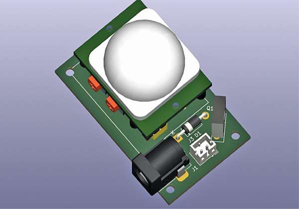
 Virtually all eating places have handwash sink for using their prospects. Since it’s utilized by quite a few folks, the faucet stops working correctly after a while and begins leaking, resulting in wastage of water. This circuit can forestall the issue because it lets the water movement from the faucet routinely solely when an individual comes earlier than the sink.
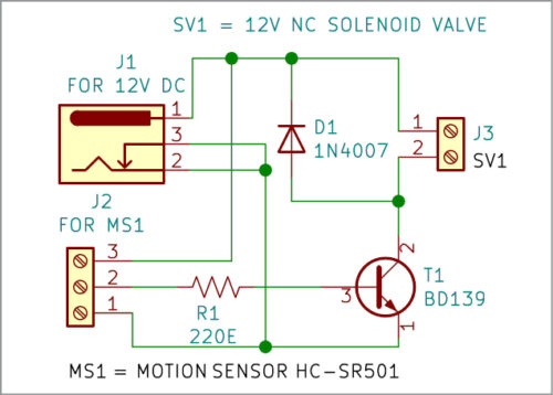
The circuit is constructed round a DC barrel jack (J1), PIR sensor HC-SR501 (MS1), transistor BD139 (T1), a normally-closed solenoid valve (SV1), and some different parts. The circuit may be powered by a 12V battery or an exterior 12V DC adaptor.
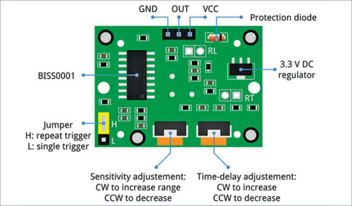
Earlier than understanding the working of the challenge, allow us to perceive working of the PIR movement sensor, which is the center of this circuit. Fig. 2 exhibits the entrance aspect of PIR movement sensor whereas Fig. 3 exhibits its again aspect.
HC-SR501 is low-cost passive infrared sensor used to detect any sort of movement. It has broad working voltage of 4.5V to 20V and two working modes—repeatable mode and non-repeatable mode.
In repeatable mode (H: repeat set off in Fig. 3), the sensor output goes excessive when movement is detected. It stays excessive so long as the individual is within the vary of the sensor. When the individual strikes out of its vary, its output goes low—after a pre-set time.
In non-repeatable mode (L: single set off in Fig. 3), the sensor output goes excessive just for the pre-set time when movement is detected. Any motion throughout this era doesn’t have an effect on the output, so water retains flowing throughout this era. It triggers solely as soon as and isn’t re-triggered. On this challenge,we’ve got used the repeatable mode.
On again aspect of the sensor there’s a jumper and two variable resistors, as proven in Fig. 3. The jumper is used to pick out the working mode. One variable resistor is used to differ the sensitivity of the sensor and the opposite to differ its time delay.
Working of the circuit is easy. Usually, the sensor output is low, and the valve is just not energised. When an individual is available in entrance of the PIR movement sensor, the sensor’s output turns into excessive so long as the individual is throughout the vary and energises the solenoid coil. The valve opens and water begins flowing from the faucet.
| Components Listing |
| Semiconductors: D1 – 1N4007 rectifier diode T1 – BD139 NPN transistor Resistors (all 1/4-watt, ±5% carbon): R1 – 220-ohm Miscellaneous: J1 – DC barrel jack J2 – 3-pin terminal connector J3 – 2-pin terminal MS1 – HC-SR501 PIR movement sensor SV1 – 12V NC solenoid valve, Single-changeover relay |
When the sensor detects nobody inside its vary, its output turns into low, and the solenoid coil will get de-energised. Thus, water flows from the faucet solely when somebody is inside its vary and stops routinely when an individual strikes away.
Development and testing
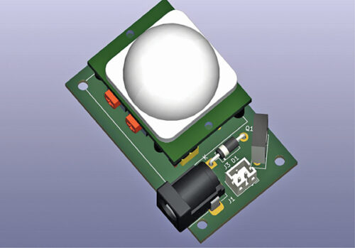
Being fairly easy, the circuit may be assembled on a general-purpose PCB. After assembling the circuit, enclose it in an acceptable field. Set up the movement sensor in entrance of the handwash sink in such away that when somebody is available in entrance of it, the faucet water begins flowing.
In non-repeatable mode (L: single set off in Fig. 3), the time for water movement may be pre-set by means of the time-delay adjustment pot (on proper hand aspect in Fig. 3). Sensitivity may be set by sensitivity-adjustment pot (on left hand aspect in Fig. 3).
EFY Notes.
- Repair the solenoid valve in correct water movement course. The course is marked within the valve housing.
- There’s a minimal strain required for correct functioning of the valve. The the water storage tank must be at a top of a minimum of three metres above the valve, in any other case use of a water strain pump could be required.
A. Samiuddhin, a circuit designer, is B.Tech in electrical and electronics engineering. His pursuits embody LED lighting, energy electronics, microcontrollers, and Arduino programming

