Moving into Wayfinder, the brilliant new RPG sport by the writer of Warframe and a studio of former Darksiders devs, is like entering into the fantasy world I all the time needed. Because the curtains half to unveil the Stormwind-esque hub space of Skylight, my internal WoW participant goes wild – it’s the Alliance stronghold if it had the graphical overhaul I’ve been ready for. Past these nice first impressions, nevertheless, there are nonetheless a couple of creases to be ironed out.


Skylight is a bastion in opposition to the ominous Gloom, a hostile environmental pressure that has overtaken a lot of the world, opening up twisted mirror realities in its wake. There’s a ye olde-style tavern, a babbling brook, and an enormous portal (the aptly entitled ‘Gloom Gate’) that takes you out to journey within the harmful unknown.
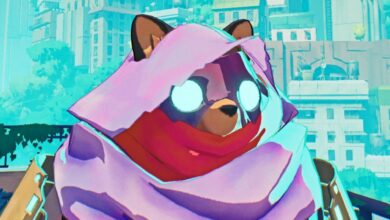
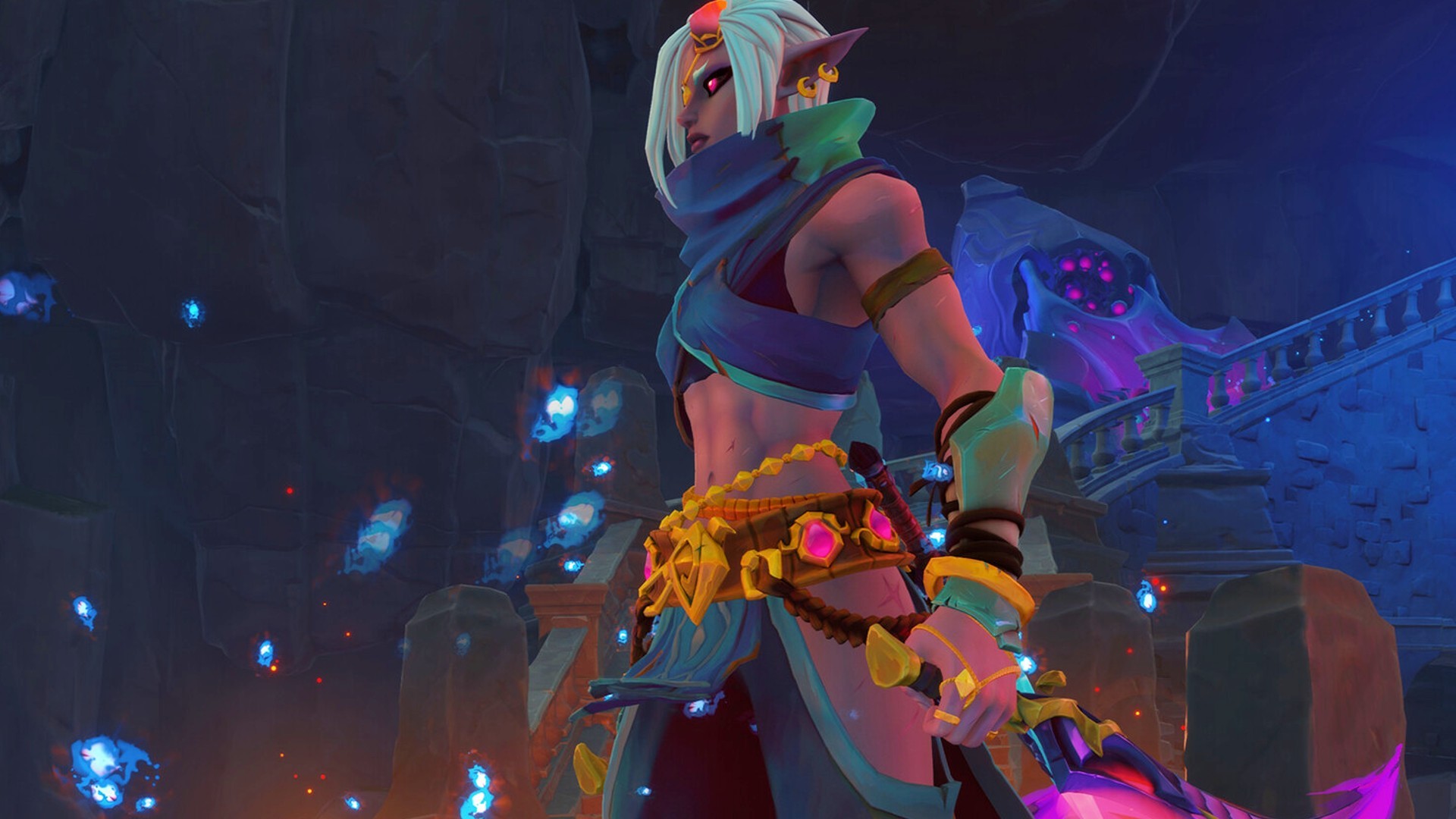
I select to run my first mission as Niss, a tortured Shadow Dancer whose thirst for vengeance outweighs her hatred for the human-dominated world round her. Described by design director and Airship Syndicate co-founder Steve Madureira as a “glass cannon” murderer who, whereas squishy, offers tons of injury, I knew instantly that she was the one for me. Plus, her character design is totally beautiful, in order that helps.
You select from a roster of heroes in Wayfinder. Not like World of Warcraft or Last Fantasy XIV, you don’t design your individual hero, however you possibly can customise your favorite character’s outfits to make them extra you. It’s also possible to tinker along with your character’s weapons, power-ups, and far, far more. What the sport lacks in character creation it makes up with a versatile means system that can make it easier to mould characters to your distinctive playstyle. I’m going with Niss’ twin daggers to start out with, purely as a result of they give the impression of being so rattling cool.
The sport’s look is apiece with a tried-and-true artwork fashion of vibrant colors and neatly exaggerated proportions. Not like so many action-adventure video games and MMORPGs of the post-Souls period, this isn’t all gloom and grit, however neither is it fairly as chunky and Disney-fied as World of Warcraft – there’s element and complexity, notably within the environments, that’s paying homage to basic Last Fantasy with out going full anime like FFXIV. It’s an ideal mix of RPG aesthetics, and boy, am I right here for it.
As we plunge into The Pit (the sport’s second Misplaced Zone) the brilliant, placid plains of Skylight are changed by an underground realm smothered by a sickly inexperienced mist. Our enemies are slimes, however they’re not cute little Slime Rancher 2 slimes; as a substitute they’re notably vicious little balls of inexperienced gunk. As Niss I hack, slash, and tear my manner by means of their ranks, watching them pop with a sick sense of satisfaction and pleasure; however belief me after I say that these slimes got here again to chunk me.
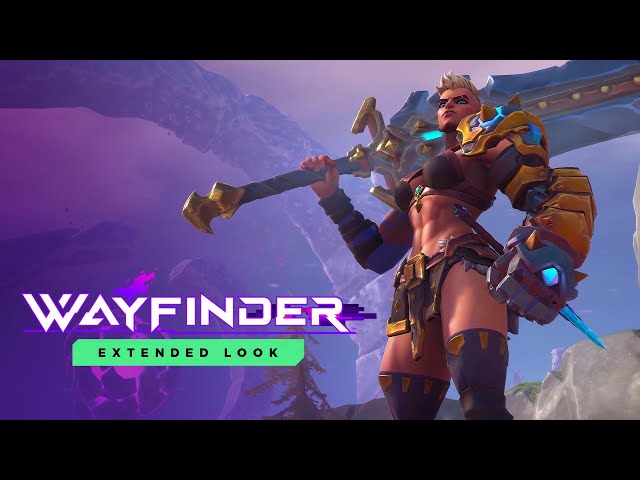
Our second outing is to a Hunt – a boss struggle a la Last Fantasy XIV’s Trials – for which Madureira admits we had been barely under-leveled. I select to play as ranged rifleman Silo, and plunge again into the mines to tackle a a lot bigger, a lot nastier slime referred to as ‘The Bloodspawn.’ Avenging its fallen comrades, stated bouncing ball of evil popped my well being bar simply as I had popped theirs, and it was in all probability simply as happy with itself as I had been not ten minutes earlier than.
Our ultimate journey out into the wilds is on a mutated run of The Pits, which is successfully the Mythic+ of Wayfinder with a slight twist. Gamers will choose up Imbuements on their journey, which could be slotted into dungeons to alter up the mechanics inside. Madureira chooses ‘Overgrowth,’ which spawns a poisonous acid pool upon an enemies’ grave that expands to fill all the accessible flooring house for those who stand on it. Assume ‘the floor is lava,’ however like, actually. It’s enjoyable, it’s chaotic, and it actually enhances the entire expertise. There’s extra to consider, and making an attempt to not step in stated poisonous muck by chance isn’t any simple job.

Having wiped after we stuffed a choke level with goo, our session involves an finish, and whereas I left largely excited I’d be a liar if my hype wasn’t certified. Whereas enjoying as Niss felt very fluid – her talents and appears remind me of League of Legends’ Pyke – I did have a couple of random digital camera bugs that messed with my imaginative and prescient, leaving me susceptible to encroaching beasties. And after I swapped to Silo and Senja, issues obtained somewhat clunky. Each characters’ motion felt very programmed, which means as a substitute of pivoting they merely ran immediately alongside the compass factors, pulling me out of the immersion.
I additionally left the session wanting extra, in each the optimistic and the unfavorable sense. Whereas I loved the situations I examined, I really feel like one thing is lacking – that je ne sais quoi, because it had been. However I’m nonetheless on board; I wish to dive again in, I wish to discover the world, I wish to see extra. They’re two conflicting emotions, however I reckon the previous could also be put to mattress the following time I get an opportunity to indulge the latter.
As future betas are introduced I’d encourage you to check out Wayfinder for those who’re on the lookout for a cool new multiplayer sport to play with associates. It’s under no circumstances good, however when Skylight requires help, I do know I’ll be strapping on my gear and diving into The Gloom head first.