 Radio detection and ranging (radar) programs detect the presence and distance of objects utilizing radio frequencies. The gap of an impediment is calculated from the time taken for the radio waves to journey to the item and, after reflection from it, return again. Gentle detection and ranging (lidar) programs work a lot the identical method; the one distinction is that they use laser mild as an alternative of radio waves.
This straightforward and inexpensive undertaking makes use of the idea of discovering an object utilizing a lidar module. The VL53L0X lidar sensor module used right here is out there as a breakout board.
The lidar module sends laser pulses and calculates the gap of an object from it utilizing the time of flight. It oscillates to search out the impediment inside its vary and shows the identical on a graphic liquid crystal show (GLCD).
Circuit and outline
The circuit diagram for object detection utilizing lidar is proven in Fig. 1. The GLCD display used right here has 128×64-pixel decision and is split into two equal halves of 64×64 pixels. By altering CS1 (pin 15) and CS2 (pin 16) pins of GLCD, the left and proper elements of the display are activated to show the information. The info and command are of 8-bit size (one byte) and differentiated by choosing standing of RS pin. Preset VR1 is used to regulate GLCD display’s distinction.
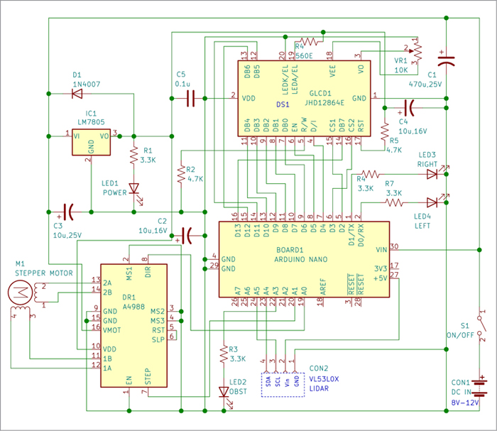
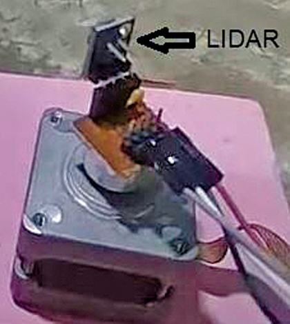
The lidar module is fitted on the shaft of a stepper motor (see Fig. 2). The chosen stepper motor has small NEMA17 body dimension with 1.8-degree step and 1A coil present ranking, or as per particular person alternative. The chosen stepper motor driver module A4988 can ship as much as 2A present to the stepper motor.
The mind of the system is compact, breadboard-compatible Arduino Nano board, which makes use of floor mount ATmega328 as its microcontroller. The Arduino Nano board may be positioned on the PCB or breadboard utilizing Berg strips fairly comfortably.
Setup and utilization
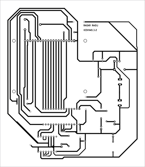
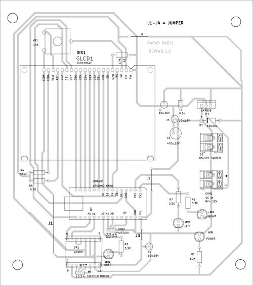
Add the sketch to Arduino Nano and join all of the parts as proven within the circuit diagram. Connect the lidar module to the stepper motor shaft with the lidar sensor going through in direction of the item. The solder-side PCB structure of impediment detection utilizing Lidar module is proven in Fig. 4 and its element structure in Fig. 5.
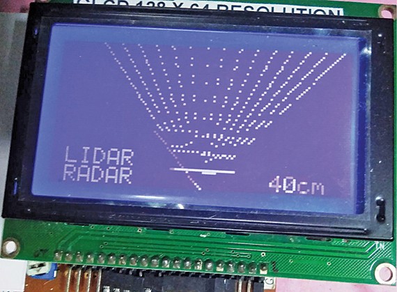
When the ability provide to the circuit is switched on by way of swap S1, the show reveals ‘LIDAR RADAR’ and the stepper motor rotates to its beginning place. Then the stepper motor shaft rotates proper and left (inside 60 levels) together with the lidar module hooked up to it to detect the item.
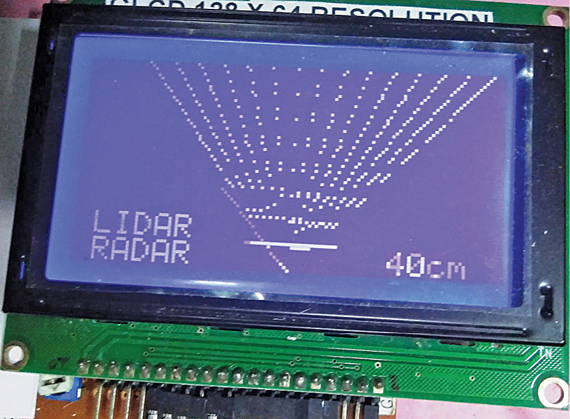
On detection, the gap of the item is learn by Arduino Nano in centimetres (cm) and displayed on the GLCD display. If the gap is greater than 99cm, the show reveals ‘OUT’ to point that the item is out of vary. The thing detected by the lidar at 40cm distance, together with the sunshine rays, is proven in Fig. 3.
There are 4 LED indicators within the circuit. LED1 is the ability indicator whereas LED2 (OBST) signifies that there’s an object inside the 99cm vary at each motion. LED3 (LEFT) and LED4 (RIGHT) point out whether or not the item is on the left facet or proper facet of the world being scanned. If the item is within the center, each LED3 and LED4 glow.
 The next factors relating to this method are value noting:
- The lidar might not detect clear obstacles as it really works on the reflection of sunshine.
- To alter the path of stepper motor rotation, simply reverse the connections of stepper motor to A4988 driver.
- The present limiting of stepper motor could also be managed by adjusting the preset on A4988 module (refer A4988 module knowledge sheet), if required.
- The next variables could also be modified within the sketch (then uploaded) to match particular person want, if any:
const int STEPPER_DELAY = 100; // delay
to settle the stepper
const int stepsPerRevolution = 200; //
set the variety of steps per revolution
to your motor
int ONESTEP=2;//variety of step indicators
despatched to A4988 per loop
Earlier than compiling and importing the code to Arduino Nano, you want following information, which may be downloaded from Hyperlink.
VL53L0X.cpp
VL53L0X.h
GLCDfont.h
license.txt
This circuit is helpful for an obstacle-detection robotics undertaking to know the gap of the impediment.
Obtain PCB and Part Structure PDFs: click on right here
Obtain Supply Code
Fayaz Hassan is Supervisor at Visakhapatnam Metal Plant, Visakhapatnam, Andhra Pradesh. His pursuits embody MCU initiatives, mechatronics, and robotics


