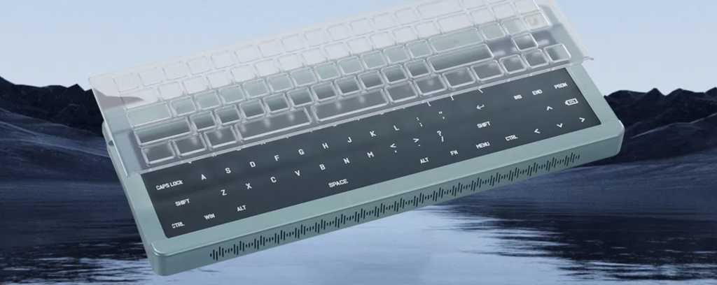
arduinoProjects

Milli-Ohm Meter With 0.1 To 1-Ohm Vary

Milli-Ohm Meter With 0.1 To 1-Ohm VaryMost shunt resistors have values under one ohm. Such low values of resistances can’t be measured reliably resulting from vary and backbone limitation of the measurement gadgets. These are often measured utilizing resistance bridges that require a particular setup.

Introduced here’s a circuit that may measure resistances of 0.1-ohm to 1-ohm. EFY lab’s prototype of the milli-ohmmeter is proven in Fig. 1.

EFY Lab’s prototype on breadboard
Fig. 1: EFY Lab’s prototype on breadboard

Circuit and dealing

Circuit diagram of the milli-ohm meter is proven in Fig. 2. The circuit is constructed round Arduino Uno board (Board1), low-dropout regulator MIC5219 (IC1), and 16×2 LCD show (LCD1).

Circuit diagram of milli-ohm meter
Fig. 2: Circuit diagram of milli-ohm meter

When present passes by way of a resistor, a voltage drop happens throughout the resistor in proportion to the present passing by way of it. By utilizing this precept, often known as Ohm’s Regulation, the resistance is measured through the use of this circuit.

The resistance to be measured is related throughout take a look at factors A and B within the circuit. The voltage drop throughout the resistor seems at analogue pin A0 of the Arduino board. The analogue reference voltage is modified to inside 1.1V reference for higher decision.

The Arduino Uno is the mind of this circuit that calculates the resistance primarily based upon the analogue-to-digital (ADC) worth and shows it on the LCD. IC1 is configured as a constant-current regulator.

When the push-to-on swap S1 is pressed, IC1 is enabled by the Arduino, and it provides fixed present of 100mA throughout the take a look at resistor. A voltage drop happens throughout the take a look at resistor whose resistance is calculated by the Arduino utilizing Ohm’s Regulation and it’s displayed on LCD1.

The resistance to be measured shouldn’t be multiple ohm. Whether it is multiple ohm, ‘!OL OR NC!’ message will seem on the LCD1.

Additionally, at any time when the resistance worth is past the one-ohm restrict, it’s disconnected from the circuit. If S1 is pressed once more after measurement, IC1 is disabled.

Arduino Uno is a well-liked open supply microcontroller improvement board primarily based on Atmega328P microcontroller. It has fourteen digital enter/output (I/O) pins of which six can be utilized for PWM outputs and 6 for analogue inputs. A 16MHz crystal, USB connector, energy jack, and ICSP header can be related to it. It comes with preloaded Arduino bootloader, so there isn’t any want of extra {hardware} to burn the Atmega chip.Part list

The circuit makes use of the software program program loaded into the interior reminiscence of Arduino Uno for operation. This system mR_Meter.ino is written in Arduino programming language often known as Sketch. An Arduino IDE is used to compile and add this system.

Building and testing

An actual-size, single-side PCB for the milli-ohm meter is proven in Fig. 3 and its element format in Fig. 4. Earlier than utilizing the circuit, don’t forget to add the supply code mR_Meter.ino by burning it into the microprocessor in Arduino Uno board.

Actual-size single side for milli-ohm meter
Fig. 3: Precise-size single aspect for milli-ohm meter

After assembling the circuit on PCB, enclose it in an acceptable field. The take a look at swap S1 ought to be mounted at a handy place within the cupboard in order that it may be used simply.

The Arduino Uno might be powered by a 9V battery or a 9V, 500mA adaptor. Use an acceptable connector for take a look at factors A and B for connecting the take a look at resistance to be measured.

Component layout of the PCB
Fig. 4: Part format of the PCB

Obtain PCB and Part Structure PDFs: click on right here

EFY notes

  1.  This circuit measures low resitances of 0.1-ohm to 1-ohm solely. There could also be an error/deviation within the measurement resulting from parasitic components within the PCB.
  2. Some other appropriate low dropout regulator (LDO) can be utilized rather than MIC5219 for IC1.
  3. A 1.5V Zener diode might be related throughout the analogue pin and floor to bypass the present supply if no resistance is related when the LDO is enabled by the Arduino.


A. Samiuddhin, a circuit designer, is B.Tech in electrical and electronics engineering. His pursuits embody LED lighting, energy electronics, microcontrollers, and Arduino programming

Leave a Reply

Your email address will not be published. Required fields are marked *

Back to top button