 A confirmed method to ship an analogue sign an extended distance is to move the sign as a frequency utilizing a voltage to frequency converter (VFC), a particular circuit whose output is a frequency that’s proportional to its enter voltage.
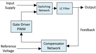
In precept, it’s comparatively simple to ship a frequency sign over an extended transmission path with out interference via optical, coaxial, or radio hyperlinks. The frequency is then reconverted to an analogue voltage by a FVC that’s normally tailor-made to carry out its inverse perform, typically utilizing a phase-locked loop (PLL). Block diagram of the undertaking is proven in Fig. 1.

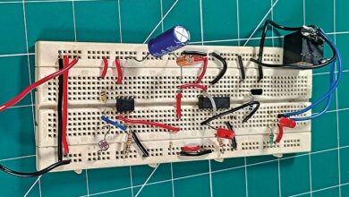
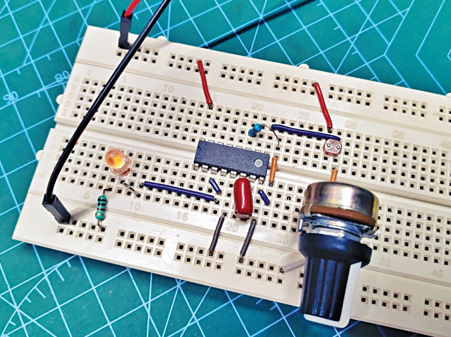
This undertaking makes use of an odd strategy to design and construct a hobby-level VFC module utilizing a handful of simply accessible and cheap digital parts. Writer’s circuit of the VFC module wired on a breadboard is proven in Fig. 2.
Schematic diagram of the VFC module is proven in Fig. 3. Please observe, a well-regulated 5V DC energy supply is completely essential to run this VFC circuit. Coronary heart of the circuit is the venerable CMOS micropower phase-locked loop IC HEF4046B.
The HEF4046B (IC1) features a VCO sub-system along with part comparators and different components. It could actually generate a sq. wave with 50% obligation cycle. The frequency in all fairness near 0Hz-1kHz vary, which is curbed by the 100nF capacitor (C1) and the 10k resistor (R1).
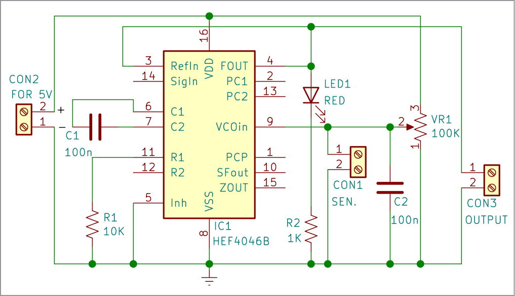
The output is obtainable on pin 4 throughout CON3. The voltage enter for the VCO on pin 9 (SEN) is related throughout CON1. CON2 is used for connecting the 5V energy provide.
As a fast apart, there’s an possibility so as to add an offset resistor between pin 12 and GND. The offset resistor needs to be bigger than the frequency-selection resistor R1, however in any other case may be infinite.
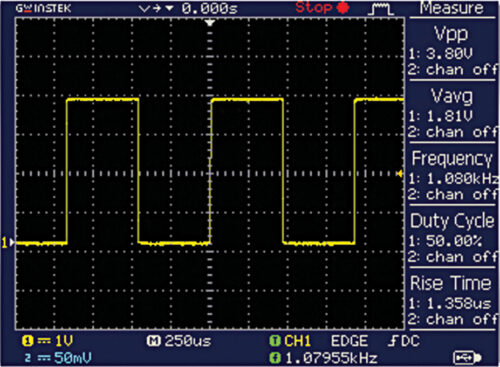
All we’d like subsequent is a straightforward variable voltage supply to check it. For that, the 100k linear potentiometer (VR1) may be connected, as proven within the schematic diagram. After which, VR1 can be utilized to fluctuate the output frequency from round 0Hz to 1kHz comfortable. Fig. 4 exhibits the frequency output at pin 4, which may be seen on an oscilloscope.
A couple of extra key issues price noting are:
- VCO output throughout CON3 is the output level of the VFC module.
- CON1 is the 0-5V DC enter connector of the VFC module.
- VR1 is an optionally available part, however it’s useful to check the VFC module. Nevertheless, after building and preliminary testing, it needs to be faraway from the setup.
- LED1 (crimson/amber) is included intentionally to offer a visible indication of the output sign. The NXP datasheet doesn’t embrace particular scores for the VCO output, however appears to cater nothing better than ~10mA. Since HEF4046B does not likely seem like tailor-made to drive any important load, LED1 can be an optionally available part.
- For the reason that voltage enter (at pin 9) of IC1 may be very delicate, if it’s not related to something, it would choose up power-line interferences and alter the frequency wildly. Including an acceptable capacitor (C2) can resolve this downside, whether or not it’s helpful or not will depend on you.
Analogue sensor check utilizing LDR (optionally available)
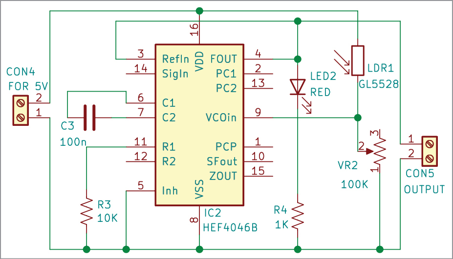
Now, allow us to do one thing that might not be accomplished with a potentiometer because the frequency management component, that’s, management the VCO frequency via an analogue sensor! To do this, observe the schematic diagram proven in Fig. 5, the place a typical GL5528 LDR (https://pi.gate.ac.uk/pages/airpi-files/PD0001.pdf) is related to the voltage enter of IC1 because the analogue sensor.
| Elements Listing | |
| Semiconductors: | |
| IC1 | – HEF4046B phase-locked loop IC |
| LED1 | – 5mm LED |
| Resistors (all 1/4-watt, ±5% carbon): | |
| R1 | – 10-kilo-ohm |
| R2 | – 1-kilo-ohm |
| VR1 | – 100-kilo-ohm potmeter |
| Capacitors: | |
| C1, C2 | – 100nF disc |
| Miscellaneous: | |
| CON1-CON3 | – 2-pin connector |
| – Breadboard | |
| Non-compulsory for Fig. 5 Circuit | |
| Semiconductors: | |
| IC2 | – HEF4046B phase-locked loop IC |
| LED2 | – 5mm LED |
| Resistors (all 1/4-watt, ±5% carbon): | |
| R3 | – 10-kilo-ohm |
| R4 | – 1-kilo-ohm |
| VR2 | – 100-kilo-ohm potmeter |
| Capacitors: | |
| C1, C2 | – 100nF disc |
| Miscellaneous: | |
| CON4-CON5 | – 2-pin connector |
| – Breadboard | |
| – LDR GL5528 | |
Right here, the photoresistor (LDR1) and the potentiometer (VR2) mix to type a possible divider, in order that the output frequency varies from 0Hz (utterly darkish) to 1kHz (robust gentle), relying on the depth of the sunshine falling on the photoresistor (see the oscillogram beneath). One other kind of analogue sensor that can be utilized here’s a thermistor; the frequency then will depend upon the temperature.
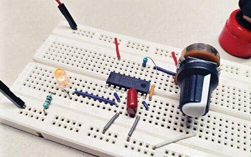
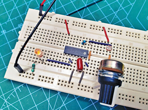
Nonetheless, the analogue sensor setup is nearly the identical performance because the potentiometer-tuned voltage managed oscillator from earlier than. Nevertheless, VR2 doesn’t play an important function at the moment, so it might be substituted with a 100k fastened resistor. (It’s fairly simple if you recognize what you’re doing.) Fig. 6 exhibits the VFC module with LDR (optionally available) wired on a breadboard.
EFY observe. That is only a design idea for a crude, hobby-level VFC module. The truth is, an actual VFC circuit is considerably completely different than this. Understand that VFC is a particular kind of VCO designed to be very linear over a variety of enter voltages, and it options many benefits and enhanced efficiency specs, which a VCO doesn’t have. There are higher designs on the market, however all of them most likely demand devoted ICs like AD654.
T.Ok. Hareendran is an electronics designer, {hardware} beta tester, technical writer, and product reviewer

