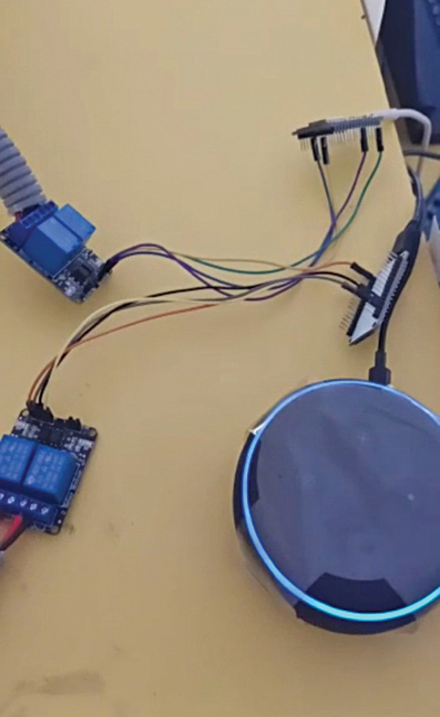
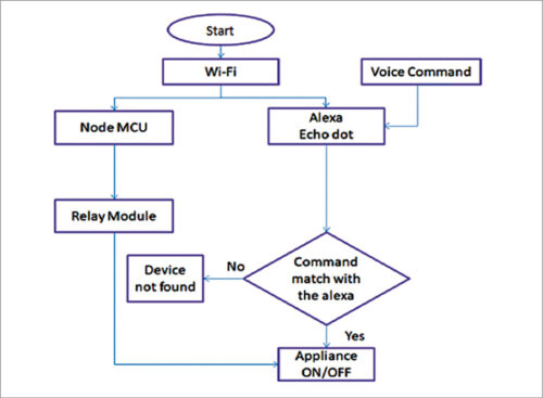
 This challenge presents a voice primarily based dwelling automation system that can be utilized by in another way abled individuals, geriatrics, and the others to regulate dwelling home equipment and thus convert a non-smart dwelling into a sensible dwelling. To attain this in a easy approach, Amazon Echo is used to speak with the circuit to regulate the home equipment.The controller used for the automation on this challenge is NodeMCU. When a command is given by the consumer to Alexa, NodeMCU will get the data by way of Wi-Fi and decides the switching motion to be taken with respect to {the electrical} home equipment linked to it by way of relays.
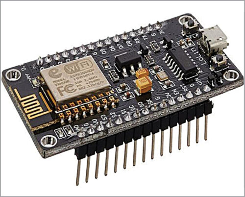
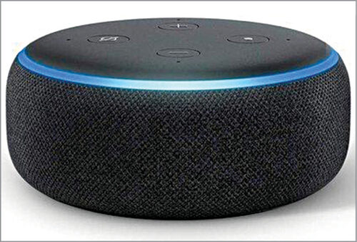
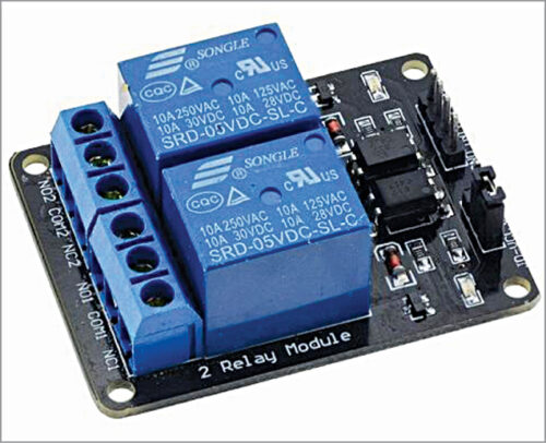
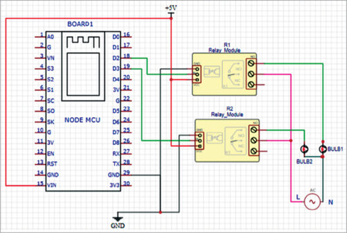
Important elements used within the challenge are proven in Fig. 1 by way of Fig. 3, whereas circuit diagram of the house automation system utilizing Alexa is proven in Fig. 4. NodeMCU used because the controller board is pre-programmed to attach with the Wi-Fi community after which take the instructions from Alexa to carry out the duties as per directions within the code, like turning on or turning off the lights or followers.
Join enter pins IN1 and IN2 of the 2-channel relay to digital pins of the NodeMCU as per the code. In case you are controlling pins D2 and D3 of NodeMCU utilizing Alexa, then the relay IN pins needs to be linked to the identical D2 and D3 pins.
The bottom pin in NodeMCU and the relay are linked equally; the Vcc pin of relay is linked to Vin of NodeMCU. Vcc and GND pins of NodeMCU are linked to exterior 5V DC provide. One terminal of the equipment is linked on to the relay (usually open) and the opposite is in collection with 220V AC provide and the relay pin (widespread).
| Invoice of Materials | ||
| Parts | Description | Amount |
| Amazon Alexa Eco Dot | Alexa primarily based sensible speaker | 1 |
| NodeMCU | Microcontroller board | 1 |
| 5V, 2-relay module (R1, R2) | 1A, 110V-220V AC relays | 1 |
| B1, B2 | 230V AC, 60W bulbs | 2 |
| Wires | Feminine to feminine jumper wires | 4 |
Software program
The software program used for this challenge is Arduino for the microcontroller and Sinric from Alexa app to interface with the {hardware}. Set up the Arduino software program after which set up the mandatory boards required for NodeMCU, as proven in Fig. 6.
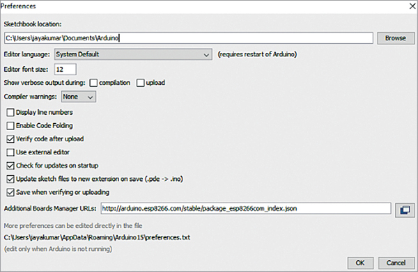
Subsequent, copy the beneath hyperlink and paste it in Boards Supervisor: Hyperlink
Click on OK to shut the choice tab. Go to Instruments and Board, choose Board Supervisor, and navigate to ‘esp8266 by esp8266 community’ and set up the software program for Arduino from there.
We are actually able to program our NodeMCU with Arduino IDE. So, now we have to set the Sinric to get our Alexa and NodeMCU linked to one another.
Set up Alexa app in your Android or iOS and full the setup of Amazon Alexa. Open Chrome or Firefox and replica the hyperlink www.sinric.com, which on clicking seems as proven in Fig. 7.
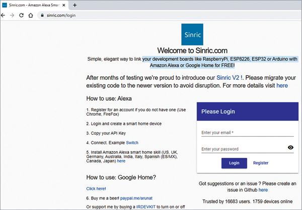
Register for a free account and login into this account. There you could find your API key, which is exclusive, and choices to generate sensible dwelling units.
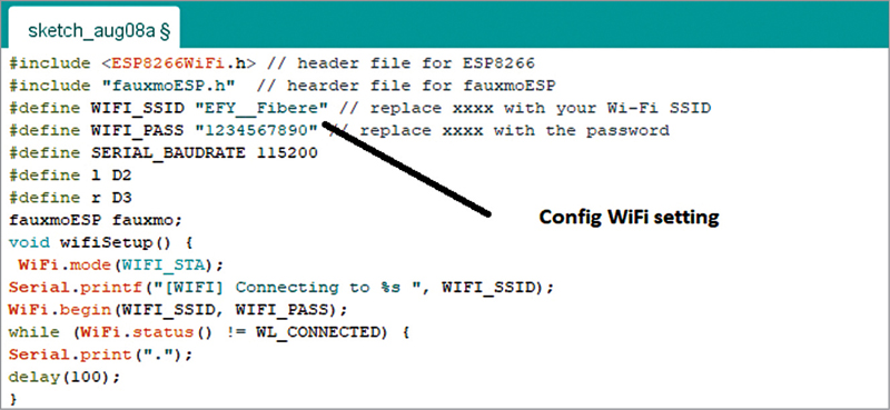
Create the code for NodeMCU. Open the .ino code file (verify supply.efymag.com) after which configure the Wi-Fi SSID and password of your property community. Within the code, choose the NodeMCU board and add the code to the board. Picture of the code snippet setting Wi-Fi and password is proven in Fig. 8.
Building and testing
Subsequent step is to interface the NodeMCU with Amazon Alexa Eco. Begin discovering the units by saying “Alexa discover devices.” The found units will get displayed within the app, as proven in Fig. 9. Please make sure that the Wi-Fi SSID and password for NodeMCU and Wi-Fi to which Alexa is linked are the identical.
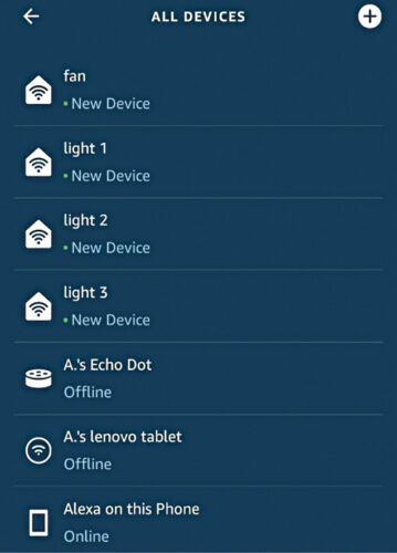
Now, we will ship instructions to Amazon Echo. Alexa will reply to the next instructions:
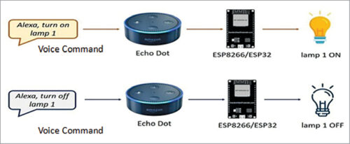
“Alexa, turn on light 1”
“Alexa, turn off light 1”
“Alexa, turn on light 2”
“Alexa, turn on light 2”
“Alexa, turn on light 3”
“Alexa, turn off light 3”
“Alexa, turn on fan”
“Alexa, turn off fan”
While you say “Alexa, turn on light 1,” the esp8266 will set off a relay to activate gentle 1. While you say “Alexa, turn off light 1,” the esp8266 will ship a sign to the relay to show off gentle 1, as proven in Fig. 10. This works equally for gentle 2, gentle 3, and the fan.
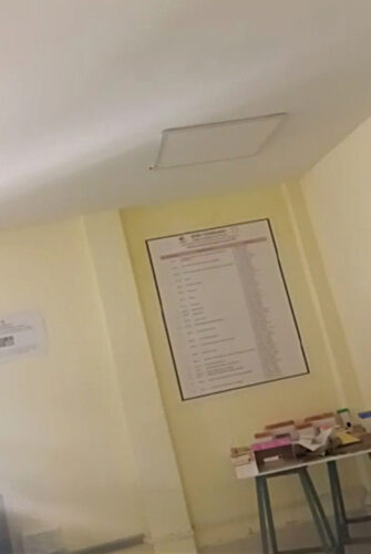
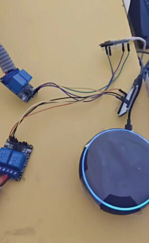
Fig. 11 exhibits tips on how to give command to Echo Dot, Fig. 12 and Fig. 13 present the sunshine’s standing (on and off) earlier than and after giving the instructions to Alexa.
Obtain Supply Code
N.M. Sai Krishna, Assistant Professor at BVRIT Hyderabad Faculty of Engineering for Girls, is an IoT and Embedded Methods fanatic. R. Priyakanth, Affiliate Professor on the identical faculty is an IoT, Embedded Methods, and Sign Processing fanatic. A. Pranava is last yr scholar on the faculty.

