Should you want to monitor and management the temperature of the water, or every other liquid for that matter, this water temperature controller might be of assist. It is going to allow you to set the utmost temperature to which the water must be heated, show the temperature at any stage of the heating course of, give indications by way of a buzzer and LED on reaching the specified temperature, and change the heater off.

Most storage-type water geysers obtainable out there for house use have such options, however some water heaters – particularly rod-type water heaters – don’t present these services. They carry on heating water until they’re switched off and thus devour a lot of electrical energy, unnecessarily, and in addition warmth the water rather more than desired.
Elements Required:
| Components Checklist | |
| Semiconductors: | |
| IC1 | MCT2E optocoupler |
| LED1, LED2 | 5mm LED |
| D1 | 1N4007 rectifier diode |
| Resistors (all 1/4-watt, ±5% carbon): | |
| R1-R3 | 330-ohm |
| R4 | 4.7-kilo-ohm |
| VR1 | 10-kilo-ohm pot |
| Miscellaneous: | |
| BOARD1 | Arduino Nano |
| DIS1 | 4-digit 7-segment show |
| S1, S2 | Push-to-on change |
| RL1 | 5V, SPDT relay |
| PZ1 | Piezo buzzer |
| CON1, CON2 | 2-pin connector |
| SENSOR1 | DS18B20 sensor |
| Water heater (1000-watt | |
Water Temperature Controller – Block Diagram
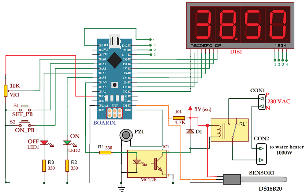
The block diagram of this easy challenge is proven in Fig. 1 and its circuit diagram is in Fig. 2. The challenge is constructed round water temperature sensor probe DS18B20, a 4-digit multiplex 7-segment show, Arduino Uno board having microcontroller ATmega328, optocoupler MCT2E, a potentiometer (pot), LEDs, a mini buzzer, and relay.
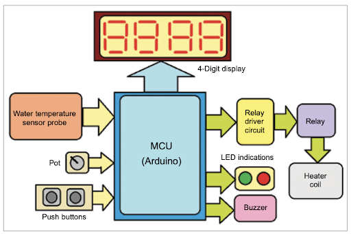
The water temperature sensed by the probe might be seen on the 4-digit show. You’ll be able to set the required water temperature utilizing the pot and change on the relay to start out heating water. When the water temperature reaches the set degree, the relay will robotically flip off and the heating of the water will cease.
The one-wire sensor probe DS18B20 from Dallas beneficial for the challenge senses the water temperature and offers the direct digital worth of temperature studying utilizing a particular one-wire protocol. Pot VR1 is used to set the required water temperature. DIS1 is a 4-digit multiplex 7-segment show that helps set the required water temperature and know the temperature at any stage. LED1 and LED2 are heaters on/off indicators. The buzzer produces a ‘beep’ sound on reaching the set water temperature. The relay driver circuit (constructed round MCT2E) supplies isolation and safety in addition to driving the relay.
The 10k pot (VR1) is related between the 5V and GND pins of the Arduino board with its central slider terminal related to analog enter pin A0. This offers 0 to 5V analog enter to the Arduino board. Push-button switches S1 and S2 are related to pins A1 and A2 such that when a change is pressed, the corresponding pin is grounded and offers logic 0 enter. The 2 LEDs (crimson and inexperienced) are related to pins A3 and A4 with their cathodes related to the bottom by way of 330-ohm current-limiting resistors.
Pin A5 of Arduino Board1 is related to the anode pin of the LED in optocoupler MCT2E by way of 330-ohm present limiting resistor R1. The output of the transistor within the optocoupler drives the relay. A reverse freewheeling diode is related throughout the relay coil.
Mini buzzer PZ1 is related to digital pin D0 of the board, with its + enter related to pin D0 and – enter related to the bottom. Sensor probe DS18B20 has three interfacing pins marked as +V, OP, and GND. The +V pin is given a 5V provide (exterior), the GND pin is related to the circuit’s floor, and the OP pin is related to digital pin D1 of the board. A 4.7k pull-up resistor is related between +V and OP pin, as beneficial within the datasheet for the DS18B20 sensor.
The 4-digit multiplex 7-segment show is a common-cathode kind; its frequent pin is related to the bottom. Its eight phase inputs (A, B, C, D, E, F, G, DP) are related to digital pins D2 by way of D9, and its digit choose pins 1 by way of 4 are related to digital pins D10 by way of D13.
Arduino Nano performs virtually all of the duties. It reads the temperature worth from the DS18B20 probe. Takes consumer inputs from the pot and switches. Exhibits water temperature on the show. Provides indications by way of the LEDs and buzzer. And it switches the heater on and off.
Water Temperature Controller – Working
Engaged on the challenge is straightforward. Initially, the heater is off and crimson LED1 is on to point it. So, it’s possible you’ll set the required water temperature utilizing the pot and press the SET push-button. You could set the temperature from 40 to 70°C, which might be seen on the 4-digit show (like 45, 48, 55, 65, and many others.).
As soon as the required temperature is ready, the heater is switched on by urgent the ON push-button. Inexperienced LED activates to point the heater is on. Now the show reveals the present water temperature. Because the water temperature rises, the show reveals the rising water temperature. When the water temperature reaches the set temperature, the heater turns off, producing a beep sound. The crimson LED activates once more.
Programming
This system is written in C/C++ language utilizing Arduino IDE. Three libraries are utilized in this system: OneWire.h, DallasTemperature.h, and SevSeg.h. OneWire.h is used for the one-wire protocol to learn the info utilizing a single wire. DallasTemperature.h is used to learn temperature from the DS18B20 sensor. SevSeg.h is used to point out the temperature on the 7-segment show.
This system is compiled utilizing Arduino IDE and uploaded into the inner flash reminiscence of the Arduino board’s microcontroller ATMega328.
Obtain Supply Code
Water Temperature Controller – Circuit Diagram
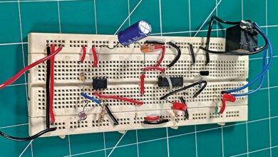
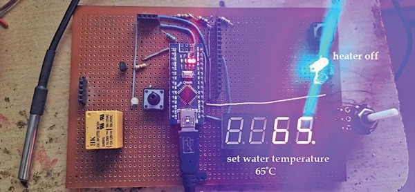
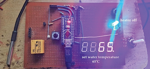
After importing the supply code into the inner EEPROM (flash reminiscence) of the Arduino Nano board, assemble the circuit on a general-purpose PCB. Don’t forget to interconnect factors 1, 2, 3, and 4 proven in Fig. 2. Earlier than meeting, seek advice from the creator’s prototype proven in Fig. 3 to know the way to assemble the challenge. After assembling the circuit on PCB, enclose it in an acceptable field. Repair LED1 and LED2 on the entrance aspect of the field and prolong the sensor to the water tank with appropriate wires.
The water temperature setting is important. The pot is used to set the water temperature between 40 and 70°C. Because the pot is rotated, it provides analog enter of 0 to 5V at pin A0. The interior 10-bit ADC of the ATMega328 microcontroller converts this analog voltage right into a digital worth of 0 to 1023. This 0 to 1023 vary is mapped right into a corresponding temperature vary of 40 to 70°C, which is proven on the show.
SET and ON push-button switches give logic enter 0 to pins A1 and A2 (digital pins 14 and 15) when pressed. SET is pressed when the required water temperature is ready by way of the pot. This units the temperature restrict until the water can be heated. Urgent ON the pushbutton switches the heater on and begins heating water.
When the ON button is pressed, logic 1 is given to pin A5 (digital pin 19). This switches on the relay by way of the optocoupler. Because the relay is switched on, the heater coil will get 230V and begins heating water. Inexperienced LED is turned on by sending logic 1 to pin A4 (digital pin 18) to point the heater is on.
The heating water’s temperature is sensed by the DS18B20 probe, which supplies a temperature studying to Arduino. Arduino reveals this temperature on show.
When the water reaches the set temperature, logic 0 is shipped to the board’s pin A3, the relay switches off, and thus the heater turns off. Concurrently, the crimson LED is turned on by sending logic 1 to pin A3 (digital pin 17) to point the heater is off. Buzzer pin D0 will get logic 1 for some time (2 to three seconds) to supply the beep sound to point that the water has been heated to the extent desired.
Associated Temperature Controller Initiatives
Ashutosh M. Bhatt is M.Tech (gold medalist) in embedded methods. At the moment, he’s a lecturer of electronics and radio engineering at Authorities Polytechnic, Jamnagar, Gujarat

