
There are lots of easy RF receiver circuits accessible for AM/FM band. However the troublesome half is making the coils and tuning the circuit. With out correct development and alignment the circuit wouldn’t carry out nicely.
This text explains the right way to construct a easy stereo FM receiver with none tuning parts (inductors(L), variable capacitors(C) and ceramic IF filters).
The receiver is able to receiving 76-108MHz FM band with stereo output having good sensitivity and efficiency. The output is able to driving 32Ω speaker immediately which eliminates extra audio headphone amplifier.
The center of the circuit based mostly on HEX3653/GS1299/RDA7088. We are able to use anybody of them. The entire above three ICs having similar pinout and performance.
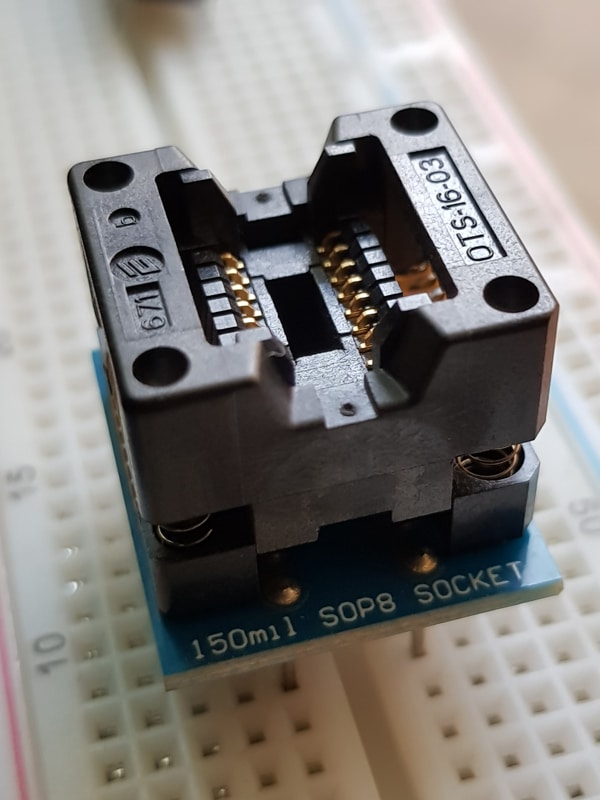
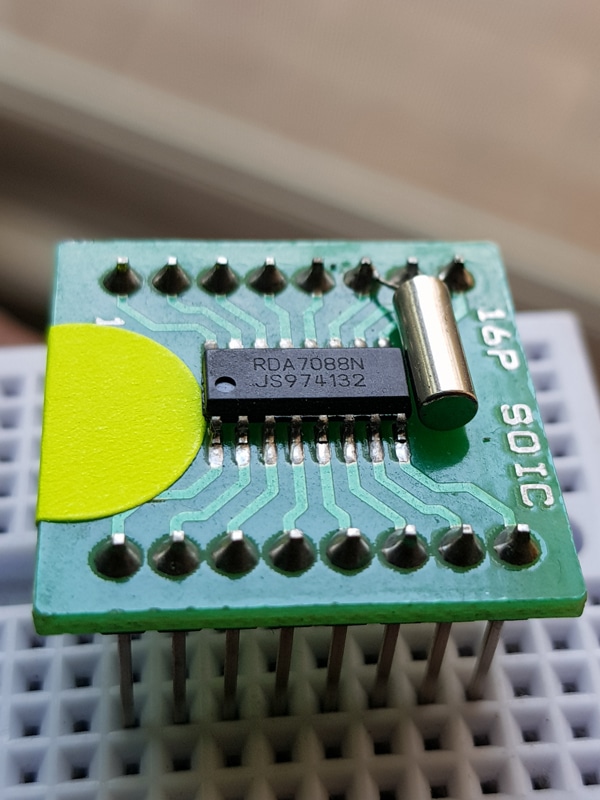
The IC is available in SOP-16 package deal with 1.27mm lead pitch. We are able to both use a pitch converter breakout board for straightforward breadboard or veroboard or dotboard utilization with 2.54mm pitch. We are able to additionally use SOIC-16 ZIF socket adapter with 2.54mm pitch for straightforward and fast experiments.
Options:
- Requires least exterior elements
- Helps worldwide frequency band 76-108 MHz
- Lower than 5s full band search time
- Low price 32.768kHz crystal for RCLK
- Digital Automated Achieve Management(AGC)
- Direct 32Ω spearkers driving functionality
- Easy SOP16 package deal
- 1.8V to three.6V DC voltage operation
- Low present consumption of 17mA at 3.0V
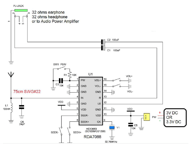
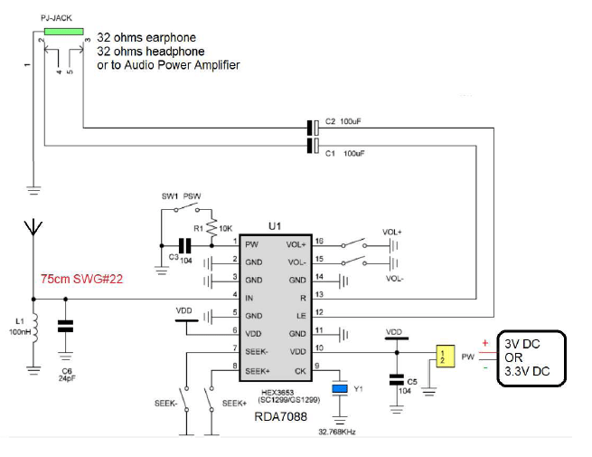
Schematic Diagram
BOM
| No. | Ref. | Desc | Qty |
| 1 | U1 | RDA7088 or HEX3653 or GS1299 SOP-16 | 1 |
| 2 | Y1 | 32.768kHz crystal (2x6mm or 3x8mm) | 1 |
| 3 | SW | Tactile change – 2 legs / 5mm pitch | 5 |
| 4 | R1 | Resistor 10kΩ / 250 mW / CFR 5% | 1 |
| 5 | C3, C5 | Capacitor 100nF | 2 |
| 6 | Antenna | 75cm SWG#22 | 1 |
| 7 | C1, C2 | Capacitor electrolytic 100uF/16V | 2 |
| 8 | L1 | Inductor 100nH | 1 |
| 9 | C6 | Capacitor 24pF | 1 |
| Breadboard or Veroboard | 1 | ||
| SOP16 1.27mm to 2.54mm adapter or ZIF socket | 1 | ||
| Jumper wires | |||
| 3V DC or AMS1117-3.3 |
Development and Connections
We are able to assemble utilizing a Veroboard or breadboard. First we have to repair the IC utilizing a 2.54mm adapter board or ZIF SOIC16 socket. For adapter board requires soldering talent to solder 16 pin 1.27mm pitch IC.
Join all of the GND(2,3,5,11&14) and VDD(6,10) pins as proven within the diagram.
Join the 32.768kHz crystal one finish to pin 9 and the opposite finish of the crystal linked to GND.
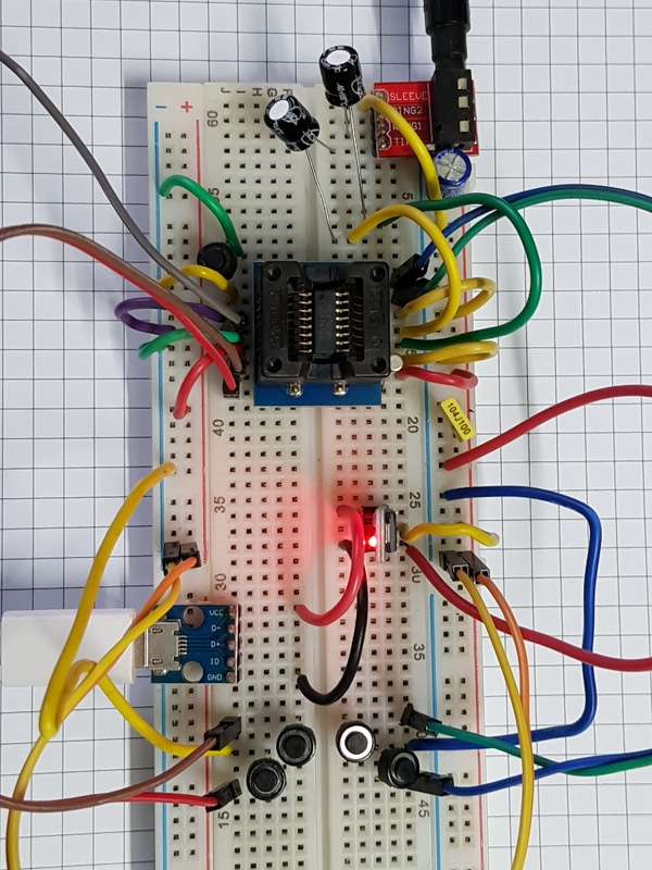
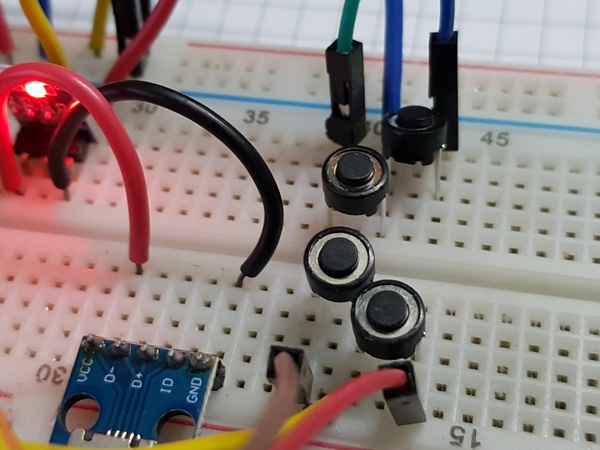
Join 5 push buttons to pin no 1,7,8,15&16 for POWER ON/OFF, SEEK-, SEEK+, VOL- and VOL+ features respectivly. Resistor R1(10kΩ) and C3(100nF) are non-obligatory and never required.
Join C1&C2(100uF/16V) to pin 12&13. The opposite finish of the capacitors C1 and C2 may be immediately linked to 32Ω speaker + terminal or linked to three.5mm audio jack. In case you join 3.5mm audio connector then we will plug earphone or headphone of 32Ω resistance sort.
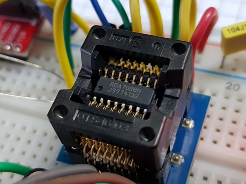
For antenna join 75cm size SWG#22 wire to pin 4 of the IC.
Inductor L1(100nH) and C6(24pF) types the band rejector. The L1&C6 parallel mixture permits 76-08MHz band and rejects beneath 76MHz and above 108MHz. L1&C6 improves the efficiency. However not necessary if availability is a matter.
We are able to additionally use the earphone or headphone wire as FM enter antenna.
For extra particulars discuss with the datasheet software circuit.
Join C5(100nF) near the pin 10 and GND.
Energy:
We are able to present 3V DC from 1.5×2 AA cells. Make certain the polarity of the ability supply whereas connecting the battery to the circuit. Else we will additionally present 3.3VDC from 5V energy adaptors with the assistance of utilizing AMS1117-3.3 breakout board.
Operation:
There are solely 5 doable features accessible with this circuit.
- POWER ON/OFF management utilizing SW1(PSW). It’s a toggle sort enter. Urgent as soon as turns the radio ON. Urgent once more turns the radio OFF.
- Urgent SEEK- searches the subsequent accessible channel in the direction of 76MHz
- Urgent SEEK+ searches the subsequent accessible channel in the direction of 106MHz
- Urgent VOL- reduces the VOLUME
- Urgent VOL+ increses the VOLUME
Is determined by the sign energy the AGC supplies constant efficiency with diminished noise.
The general efficiency of the FM stereo receiver is nice in comparison with the associated fee and variety of elements required.

