
Automating family or workplace programs will be achieved utilizing an Arduino Nano, a passive infrared (PIR) movement sensor, and a relay.
The first purpose is to create a management system that prompts or deactivates electrical gadgets in response to human motion, enhancing comfort and vitality effectivity.
The core part, the Arduino Nano, is a compact, versatile microcontroller board that processes indicators from the PIR movement sensor. The PIR sensor detects modifications in infrared radiation attributable to human presence or motion inside its vary.
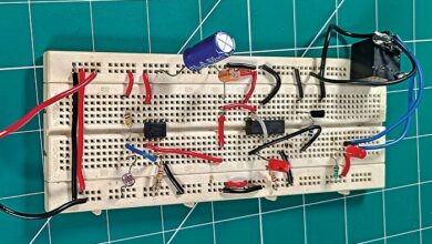
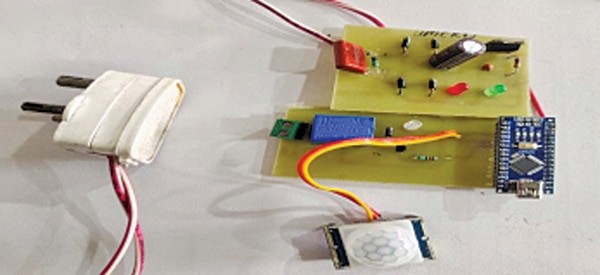
When motion is detected, the sensor sends a sign to the Arduino Nano, which processes the enter and triggers the relay. Fig. 1 shows the prototype.

The relay features as an middleman swap, controlling related gadgets based mostly on instructions from the Arduino. This configuration allows the system to activate lights when an individual enters a room and swap them off after a set interval of inactivity, thus optimising vitality utilization and person comfort.
| Invoice of Supplies | |
| Elements | Amount |
| Arduino Nano (MOD1) | 1 |
| PIR sensor (S1) | 1 |
| 230V AC to 9V, 250mA secondary transformer (U1) | 1 |
| 5V voltage regulator 7805CV (IC1) | 1 |
| Ceramic disc capacitor 100nF (C1) | 1 |
| Electrolyte capacitor 1000µF, 40V (C2) | 1 |
| 5mm LED (purple, inexperienced color) | 2 |
| Resistors 330 ohm (R1, R2) | 2 |
| 5V SPST relay (RLY 1) | 1 |
| 5V DC adaptor (optionally available) | 1 |
| 230V AC 60W bulb (as a load for testing) | 1 |
Arduino Movement Sensor – Circuit and Working
The circuit diagram of the automation system utilizing a movement sensor is proven in Fig. 2. It consists of an Arduino Nano board (MOD1), a PIR sensor (S1), a 230V AC to 9V secondary transformer (U1), a bridge rectifier, a 5V voltage regulator 7805CV, IC1 and different important elements.
A ready-made 5V adaptor can alternatively be used as an alternative of the transformer, bridge rectifier, and voltage regulator.
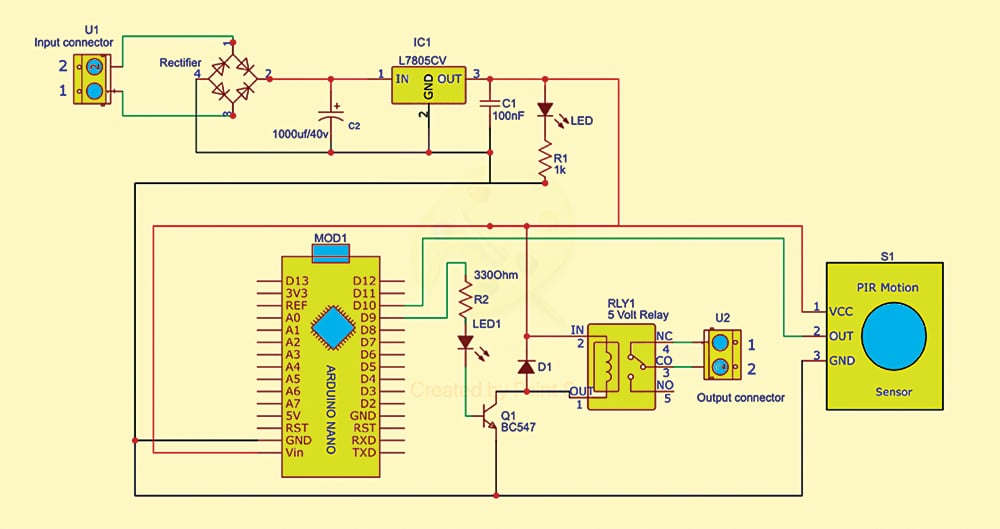
The system operates on a 5V DC provide, with capacitors C1 and C2 filtering any ripples.
The Arduino Nano serves because the controller. The PIR movement sensor detects human motion and transmits information to the Arduino. The PIR sensor has three pins: VCC, GND, and OUT.
A 5V single-pole, double-throw (SPDT) relay used to regulate the load (230V AC, 60W bulb) acts as a swap. The 5V energy provide is related to the 5V (Vin) and GND pins of the Arduino Nano to allow the circuit.
The VCC and GND are shared by the Arduino Nano, the PIR sensor module, and the relay, as illustrated in Fig. 2.
The OUT pin of the PIR sensor connects to digital pin 10 (D10) on the Arduino Nano. Pin 9 (D9) connects to the bottom of the relay driver transistor BC547 by means of resistor R2 and LED1.
The Arduino Nano processes inputs from the PIR movement sensor. When movement is detected, the sensor indicators the Arduino Nano, which triggers the relay and prompts the bulb. The relay acts as a swap to allow or disable the related 230V AC, 60W bulb in accordance with the movement sensor’s enter.
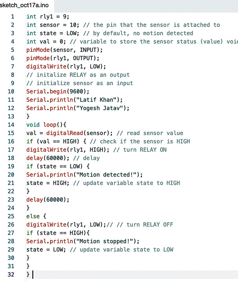
The Arduino software program platform is used to develop the supply code. The code defines the movement sensor and relay pins, setting one as enter and the opposite as output. The loop repeatedly checks for movement, and when detected, the Arduino Nano indicators the relay to activate. Fig. 3 exhibits a code snippet.
Additionally Examine: Superior Arduino Tasks for Engineers and Freshmen
Building and Testing
Assemble the circuit on a general-purpose PCB and join the secondary aspect of the transformer throughout the enter connector (U1).
As soon as the elements are related as per the circuit diagram, the system ought to be put in in an appropriate location to make sure that the PIR movement sensor can detect human motion on the major entrance.
Join the 230V AC, 60W bulb throughout the output connector (U2) because the check system. Any electrical equipment could also be used rather than the bulb to check.
After assembling, enclose the system in a cupboard for defense and correct set up. As soon as put in, the system will be powered and is prepared to be used. The first purpose of this system is to automate the management of dwelling home equipment and save vitality.
Dr Latif Khan is an assistant professor, whereas Yogesh Kumar Jatav, B.Tech, is a design engineer (CII) at Geetanjali Institute of Technical Research, Udaipur.

