
This Home windows-based program, created with Microsoft Visible Fundamental (VB6), options an intuitive person graphic interface (UGI) and operates seamlessly on the Home windows platform. It interfaces with a private laptop’s (PC’s) USB port through a {hardware} module, which features a microprocessor-based digital circuit able to controlling as much as eight home equipment by means of the PC.
This system transmits particular directions to the microprocessor-based interface card through the USB port. These directions are pre-programmed and saved within the microprocessor’s reminiscence. Actions are executed by means of a delegated relay quantity linked to an enter/output (I/O) pin of the microprocessor and driver circuit.
At its core is the ATmega328P, a single-chip, 8-bit microcontroller housed in a 28-pin DIL bundle. This microcontroller is each cost-effective and broadly accessible within the Indian market. As it’s the identical IC utilized in Arduino Uno, the ATmega328P circuit may be simply changed with an Arduino Uno board, if most well-liked.
| Invoice of Supplies | |
| Parts | Amount |
| 220V major to 15V, 1A secondary transformer (T1) | 1 |
| Rectifier diode 1N4007 (D1-D12) | 12 |
| Capacitor 1000µF, 25V (C1) | 1 |
| 12V voltage regulator IC 7812 (IC1) | 1 |
| 5V voltage regulator IC 7805 (IC4) | 1 |
| Relay 12V SPDT (RLY 1- RLY8) | 8 |
| Relay driver IC ULN2803A (IC2) | 1 |
| 5mm pink LED for energy indication | 1 |
| 1k resistor (R1) | 1 |
| Microcontroller ATmega328P (IC3) | 1 |
| 28-pin DIL IC base (optionally available for breadboard) | 1 |
| 18-pin DIL IC base (optionally available for breadboard) | 1 |
| Crystal 16MHz (X1) | 1 |
| 22pF ceramic capacitor | 2 |
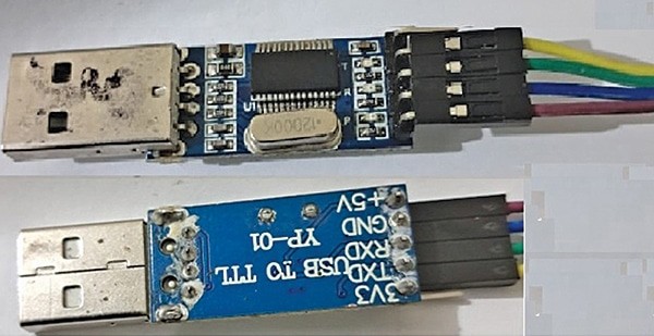
| USB-to-TTL serial converter (see Fig. 2) | 1 |
| Jumper wires | As required |
| Relay connectors | 8 |
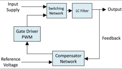
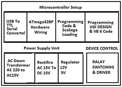
The Arduino IDE, required to program the ATmega328P, is out there totally free obtain at https://www.arduino.cc/en/software program. A block diagram illustrating this system’s performance is proven in Fig. 1, whereas the entire invoice of supplies is offered within the desk on this web page.
This program includes utilizing Visible Fundamental (VB) to speak with an exterior {hardware} module by means of the USB port. A fundamental understanding of VB programming and {hardware} information for connecting and controlling the {hardware} module is critical. A microcontroller or USB interface module acts because the middleman between the PC and the home equipment.
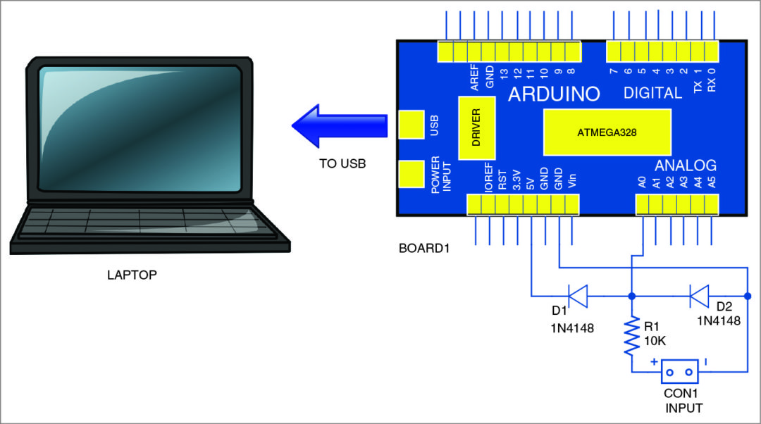
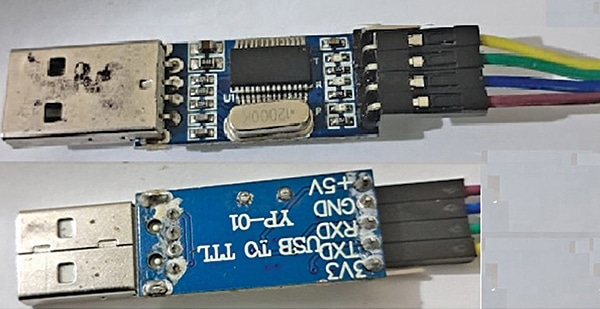
The home equipment are linked through relays. A general-purpose PCB or breadboard, jumper wires, and an influence provide for exterior home equipment are used. Fig. 2 reveals the USB-to-TTL serial converter used to program the microcontroller ATmega328P.
Circuit and dealing
Equipment management by means of the PC’s USB port utilizing Visible Fundamental is illustrated in Fig. 3. The circuit includes a step-down transformer, bridge rectifier, 12V voltage regulator LM7812 (IC1), relay driver UL2803 (IC2), microcontroller ATmega328P (IC3), 5V voltage regulator 7805 (IC4), 12 rectifier diodes 1N4007 (D1-D12), eight 12V SPDT relays, a 16MHz crystal, and different supporting parts.
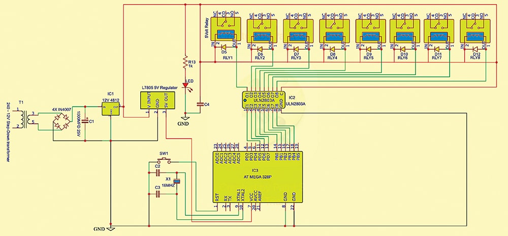
The LED signifies whether or not the circuit is powered. A 12V and a 5V regulated energy provides are required to function the circuit. These are derived from a 220V AC major to 15V, 1A secondary transformer (T1), a bridge rectifier constructed with 4 1N4007 diodes (D1-D4), and 7812 and 7805 voltage regulators. Capacitor C1 removes ripples. The 12V output from IC 7812 powers the relays and offers enter to IC 7805, whose 5V output permits the ATmega328P.
The microcontroller’s output pins are immediately linked to ULN2803A pins as per the circuit diagram to manage the home equipment through relays. The ULN2803A relay driver isolates the low-voltage circuit from the high-voltage part and controls the relay contacts.
Software program programming
Set up the IDE for VB improvement. Guarantee correct USB drivers for the microcontroller or interface module. Embody libraries for USB communication. Use input-output ports for serial communication. Two applications are used:
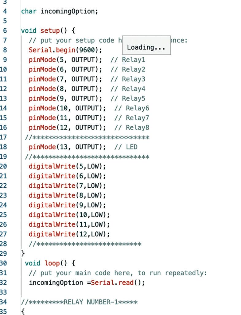
1. Arduino code sketch for the microcontroller (Fig. 4).
2. Visible Fundamental-based GUI for the PC, offering a graphical interface to manage the home equipment through the serial port.
Programming process
- Assemble the circuit based on the diagram on a breadboard or zero PCB. Confirm all connections.
- If programming by means of Arduino Uno, the USB-to-TTL serial converter is pointless.
- After programming, take away the ATmega328P IC from the Arduino Uno board and insert it into the breadboard throughout meeting. Add a brand new ATmega328P to the Arduino board.
- Run the Arduino IDE program on the PC.
- If not utilizing an Arduino Uno board, use a USB-to-TTL serial converter card to program the ATmega328P. Join the receiver pin (RXD) of the converter to the transmitter pin (TXD) of the microcontroller, and vice versa.
- Establish the Arduino port within the PC’s machine supervisor. Open the IDE, navigate to ‘tools,’ and choose the suitable board and port.
- Open a brand new sketch within the IDE, copy the code, paste it, confirm it, and add it to the ATmega328P microcontroller with a bootloader.
VB6 programming for creating GUI
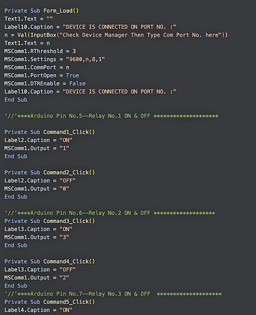
Arrange Visible Studio and create a brand new window. Add controls and the SerialPort within the toolbox. Write the VB code. Run VB6 on the PC, copy the VB6 program (Fig. 5), paste it into the brand new challenge, and create an executable (EXE) file.
Development and testing
After programming the ATmega328P IC, take away it from the Arduino Uno board. Assemble the circuit and use the programmed IC as proven in Fig. 3. Press F5 to run the VB software. Guarantee the right COM port is specified. Use the Arduino IDE’s serial monitor to confirm instructions and responses, if wanted.
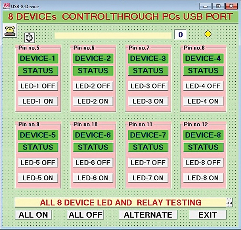
Energy the {hardware}, join the FTDI or Arduino Uno to the PC’s USB port, and run the GUI Visible Fundamental code. The GUI will seem on the display screen (Fig. 6). Management the home equipment by clicking the GUI buttons.
Adeeb Raza is an electronics engineer with about 35 years of sensible expertise. He’s an everyday reader and contributor to EFY.

