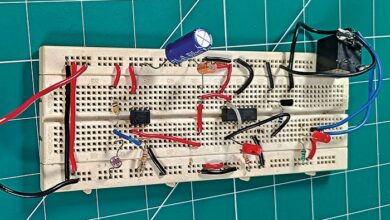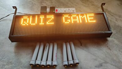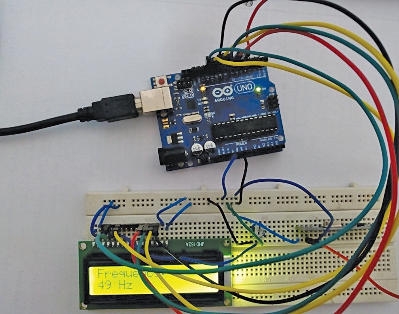

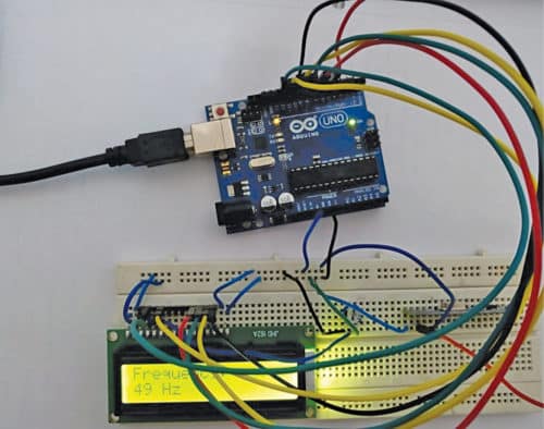
This mission demonstrates an Arduino-powered wi-fi frequency meter that may measure the frequency of sinusoidal AC transmissions starting from 50Hz to 3kHz. Figures 1 and a pair of present prototype representations of the transmitter and receiver, respectively.
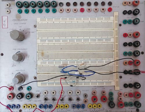
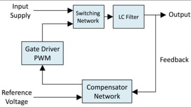
The block diagrams of the transmitter and receiver sides are proven in Figs 3 and 4, respectively.


Wi-fi Frequency Meter – Circuit and Working
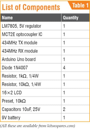
The primary parts used within the Wi-fi Frequency Meter mission and their position is described beneath.
Arduino Uno
Arduino Uno is an AVR ATmega328P microcontroller (MCU)-based growth board with six analogue enter pins and fourteen digital I/O pins. The MCU has 32kB ISP flash reminiscence, 2kB RAM and 1kB EEPROM. The board supplies the potential of serial communication by way of UART, SPI and I2C.
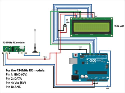
The MCU can function at a clock frequency of 16MHz. In our mission, Arduino Uno is used on the receiver facet. Digital I/O pin 5 is used as enter pin and is linked to DATA pin of 434MHz RX module. Digital I/O pins 7, 8, 9, 10, 11 and 12 of Arduino are used to interface with the 16×2 character LCD to show the worth of the measured frequency.
Rectifier Diodes
Rectifier diodes (1N4007) are used to rectify the alternating enter sign to pulsating DC on transmitter facet.
MCT2E
MCT2E opto-coupler IC is used to isolate enter facet from the subsequent stage and in addition produce indicators from pulsating DC waveform on transmitter facet.
LCD
The 16×2 LCD, current on the receiver finish, is used to show the worth of frequency. It’s interfaced with Arduino Uno board in four-bit mode. LCD pins RS, EN, D4, D5, D6 and D7 are linked to digital I/O pins 12, 11, 7, 8, 9 and 10 of Arduino, respectively.
434 MHz TX-RX Modules
The 434MHz transmitter (TX) and receiver (RX) modules are used to transmit and obtain radio frequency (RF) indicators between two units. Provider frequency of the module used right here is 434MHz.
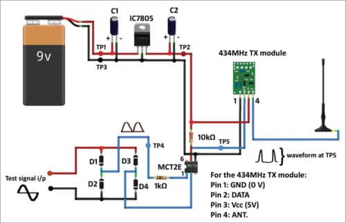
The circuit diagrams of the transmitter and receiver sides are proven in Figs 5 and 6, respectively.
Obtain supply folder: click on right here
The sign whose frequency is to be measured is utilized to check sign enter terminals, as proven within the transmitter-side circuit diagram (Fig. 5). On this frequency meter, check sign should be an alternating one and its amplitude should not be larger than 10V peak-to-peak.
The subsequent stage is a bridge rectifier, which converts the alternating sign to a fully-rectified pulsating DC sign. The sign is then utilized to pin 1 of MCT2E opto-coupler. Pin 1 is linked to anode of the interior LED of the opto-coupler.
With the assistance of the opto-coupler, spikes are produced. Frequency of the sign is twice that of check sign enter. The sign is utilized to DATA pin of 434 MHz TX.
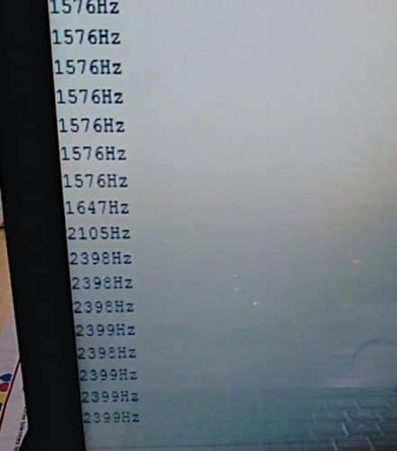
On receiver facet, 434MHz RX module demodulates the acquired sign. DATA pin of 434MHz RX is linked to digital I/O pin 5 of Arduino Uno, which calculates frequency of the check sign and shows it on the LCD and serial monitor of Arduino IDE. Take a look at sign frequencies 1576Hz and 2399Hz displayed on the serial monitor are proven in Fig. 7.
This mission can be utilized for experimenting, studying, testing and troubleshooting audio tools within the audible vary between 50Hz and 3kHz.
Arduino Code for Wi-fi Frequency Meter
Arduino IDE 1.6.5 is used for programming Arduino Uno. Choose the correct COM port and board from Instruments menu within the IDE. Add freq_meter_wl_1.ino supply code to the board.
From Instruments menu of Arduino IDE, open the serial monitor and choose the correct baud fee (9600 is used right here) to show the frequency on the serial monitor.
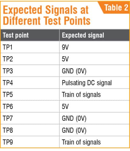
For troubleshooting, check the indicators at totally different check factors marked within the circuit diagrams. Anticipated voltages at totally different check factors are listed in Desk 2.
Additional Enhancements and Makes use of
- Software: This wi-fi frequency meter measures frequencies all through audio ranges, making it appropriate for repairing audio tools and academic settings that require wi-fi frequency switch.
- Expandability: This system can measure greater frequencies with changes to the frequency enter vary or wi-fi modules. Moreover, including further show components or incorporating SD card storage for frequency logs may improve the mission’s versatility.
Saikat Patra is enthusiastic about electronics and microcontroller-based embedded system purposes.
Shibendu Mahata is M.Tech (gold medalist) in instrumentation and electronics engineering from Jadavpur College. He’s keen on designing microcontroller-based real-time embedded sign processing and course of management programs
This text was first printed on 28 December 2019 and just lately up to date in October 2024.

