
Zener diode is a silicon semiconductor system that allows present to circulation in both a ahead or reverse route. The diode consists of a particular, closely doped p-n junction, designed to conduct within the reverse route when a sure specified voltage is reached. The zener diode has a well-defined reverse-breakdown voltage, at which it begins conducting present, and continues working repeatedly within the reverse-bias mode with out getting broken. Moreover, the voltage drop throughout the diode stays fixed over a variety of voltages, a function that makes zener diodes appropriate to be used in voltage regulation.
Many of the R&D items, academic establishments and industrial items are unable to check the Zener and bizarre diodes This DIY challenge Zener diode tester can be utilized for serviceability checks for Zener diodes and bizarre diodes. This instrument is designed with a decision of 0.01V so it’s helpful to search out out the matched pairs of zener diodes, in some crucial circuits which require matched pairs of zener diodes.
The circuit is designed with the ATMEGA328 microcontroller IC. The standalone Arduino method is adopted right here due to the recognition, economical, and simple to make use of options of Arduino IDE. This instrument can be utilized to check the zener diode as much as 33V.
Circuit and Working
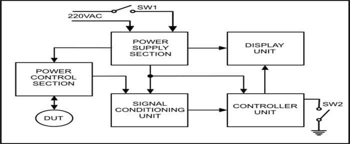
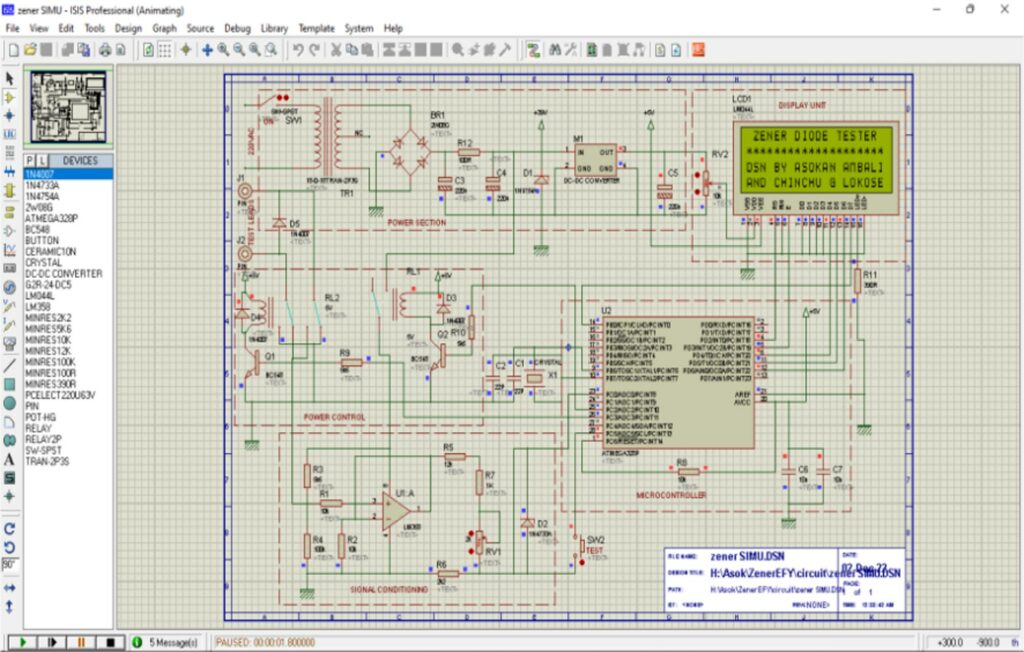
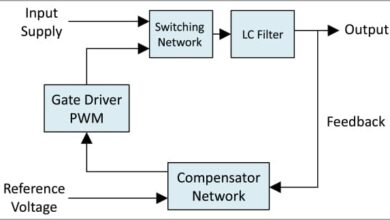
Fig 1 reveals the block diagram of the challenge. The design have 5 sections: – sign conditioning unit, micro controller, energy part, energy management and show unit.
The detailed description of the parts and modules of every sections as per the circuit diagram are defined beneath:
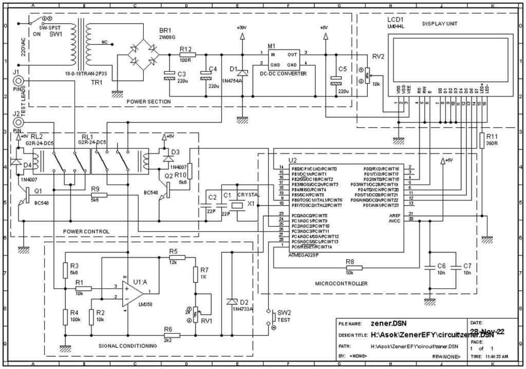
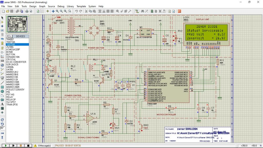
- Energy provide part: The ability provide part supplies the required provide voltages for the graceful working of the circuits. The transformer TR1. Converts 230VAC provide to 36VAC. The bridge rectifier (BR1) rectifies the AC to DC. C3, C4, C5 and R7 are linked as π filter. The capacitor C5 is linked throughout the DC-DC converter output as a further filter. The Module M1 U3 is a dc-dc converter which is used to transform excessive voltage DC to fixed 5V output. Please seek advice from the information sheet for extra data. The principle benefits of this are the excessive enter voltage (as much as 40V) and really excessive effectivity. The 5V output of this circuit is linked to the controller and show part.
- Energy management part: This part primarily has two relays RL1 and RL2, transistor Q1, Q2 diode D3, D4 and resistor R9, R10. This RL1 and related circuit are offered to modify ON the ability provide to the sign conditioning part solely when the take a look at swap is depressed. The RL2 and related circuits will toggle the availability voltage of the take a look at probe after a predetermined delay as per the software program.
- Sign conditioning unit: The sign conditioning unit converts the zener voltage to a protected degree for measuring utilizing Arduino. This part of the circuit consists of 1 Op-Amp (U1), trim pot (RV1) and resistors R1 to R7. The resistors and variable resistor are linked as a possible dividers to the Op-Amp. This part converts the voltage drop throughout the D.U.T (Diode Below Check) to 0 to 5V linear ratio. The Op-Amp is linked as a voltage follower and can be used to get most linear output voltage by using the excessive enter impedance traits of an op amp.
- The controller Unit: This part is a very powerful a part of the circuit. The ATMEGA328 (U2) is an 8 bit AVR micro controller with six inbuilt Analog to Digital Converter (ADC), six Digital to Analog Converter (DAC) and 12kb flash reminiscence. The rationale for choosing this IC is it may be programmed utilizing Arduino which is called the most well-liked and an economically viable software program growth platform. This part has few parts linked to U2 to work as a standalone Arduino. The resistor R8 used for energy on reset. The crystal CR1 Capacitors C1 and C2 are the oscillator circuits. C6 and C7 are for filter capacitors and must be linked as close to as attainable to the availability pins of the controller.
- Show unit: The LCD show (LCD1) is a 20X4 alphanumeric LCD show which can present all of the directions for testing, and the take a look at outcomes. The trim pot RV2 can be utilized to regulate the distinction of LCD.
The aim of the diode D3 and D4 that are linked in parallel to a relay coil (flywheel diode or freewheeling diode) is to keep away from damaging some close by parts delicate to excessive voltage. This voltage is generated within the coil when the present circulation is interrupted. The switch-S2 is linked to the controller to start out the take a look at.
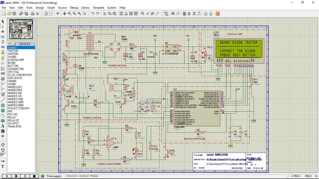
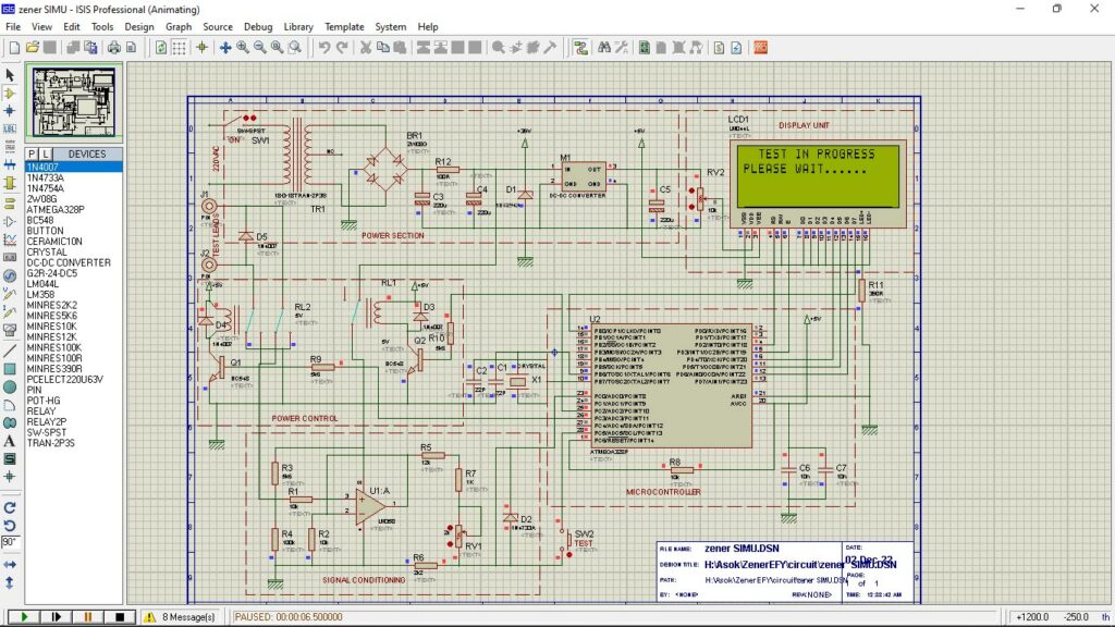
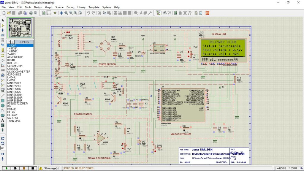
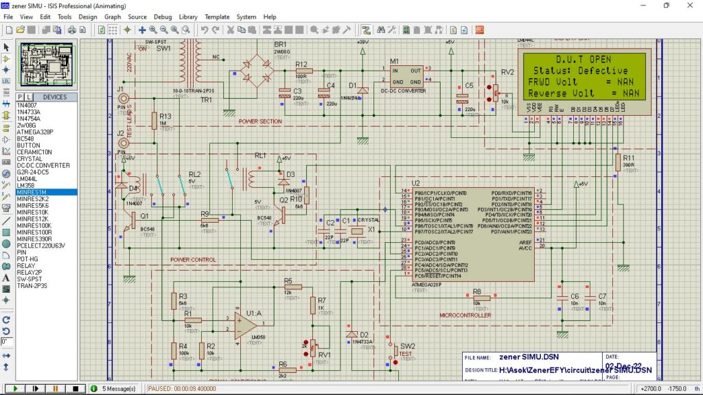
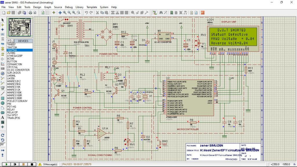
The D.U.T is linked in parallel with R4 of the potential divider R3 and R4. The voltage drop throughout the D.U.T is linked to non-inverting enter of the voltage follower the voltage can be out there on the output. The utmost output voltage is restricted to 0 to 5V for an enter of 0 to 36V. This sign conditioner is linked to the micro controller ADC (A0). The controller measures the ADC enter and shows formulated knowledge. On energy up the system will scan the take a look at swap standing and LCD reveals the required directions. A momentary urgent of the take a look at button will begin the principle take a look at program. Initially the system will measure voltage drop throughout the D.U.T and knowledge can be saved. After two seconds the relay RL2 will energize to toggle the polarity of take a look at leads and measure the voltage drop. The system will course of each knowledge and show the take a look at outcomes as sort of diode, ahead voltage, reverse voltage and the outcome (serviceable / faulty). After completion of the take a look at the availability to the take a look at lead will disconnect routinely and unit will divert again to standby mode. The consumer can edit the software program so as to add several types of diodes in keeping with their traits by referring the information sheets.
Software program
Software program is written in Arduino ”C” language. The working of the software program is properly defined in this system itself. Particular libraries utilized in software program as Liquid cystalI2C.h. Set up strategy of the third occasion header recordsdata out there in www.arduino.cc.
Development and Testing
Obtain file Supply compile sketch utilizing Arduino IDE. Join Arduino UNO to PC, choose the correct port and board. Add the sketch. Be sure that the Sketch is compiled with out errors. For additional clarification please go to www.arduino.cc.
Assemble all of the parts on PCB as proven in PCB designs. Make all of the wiring as per the circuit diagram. Cross verify for any improper connections. Take away the programmed ATMEGA328 IC from Arduino and insert the on the IC socket. Guarantee the correct orientation of the IC earlier than inserting, improper orientation will injury the chip.
Change ON 230V energy provide, ON the swap SW1 the LCD will lit up and LCD will present the welcome messages as written within the software program, If not modify the RV2 to set the distinction of the LCD. Join an bizarre diode throughout the take a look at leads and press the take a look at button. The system will measure the ahead and reverse voltages. The ultimate outcome can be displayed on the LCD display screen. The system will divert again to standby mode after few seconds as assigned within the software program.
Parts Record
| Resistors | Capacitors |
| R1,R2,R8- 10k | C1,C2 – 22pF- Ceramic Disc |
| Built-in Circuits | Diode |
| U1- LM 358 | D1-1N 4764A – 39V Zener Diode |
| Change | Terminal |
| SW1 – SPST Change | J1-J2 : Check Factors |
| Transistor | Miscellaneous |
| Q1,Q2 – BC 548 | X1- 16MHz crystal, |
| Relay | |
| RL1, RL2 5V DPDT PCB Mountable |
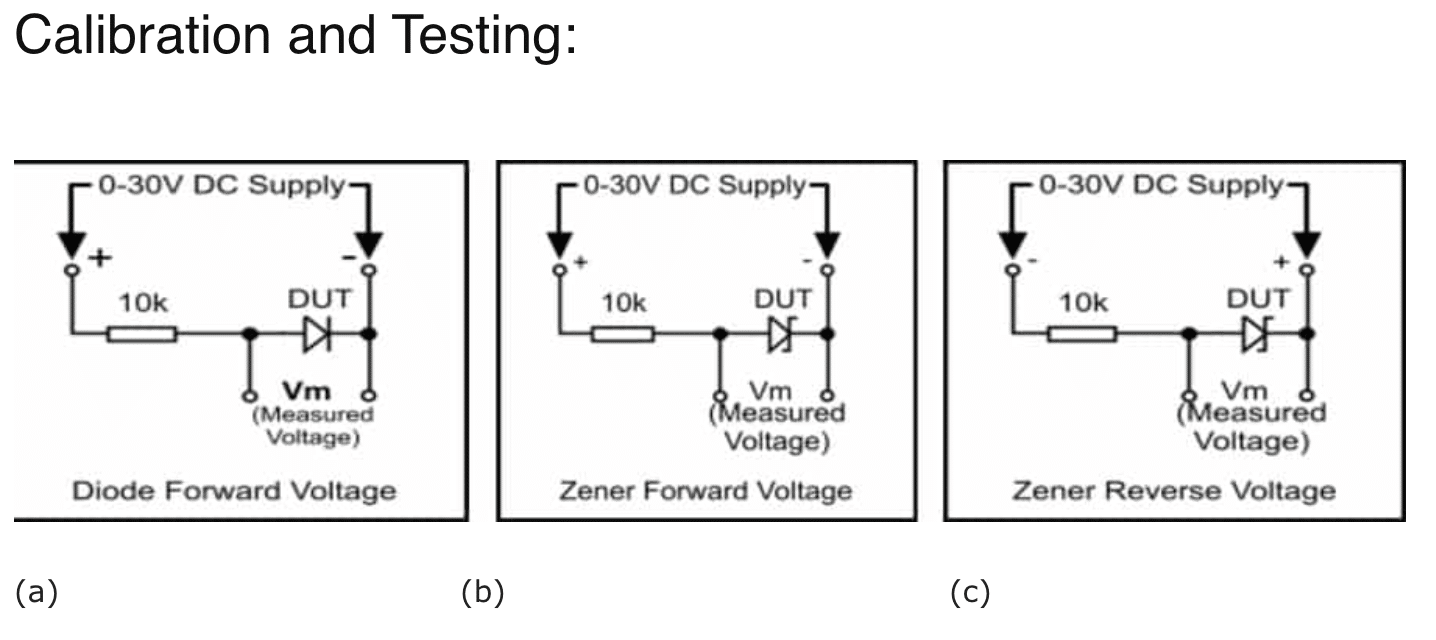
Gather one serviceable bizarre diode and a 27V zener diode. Join a 10k Resistor in sequence with the bizarre diode as proven in Fig-3(a), slowly improve the voltage to get a gentle voltage throughout the diode Measure the ahead voltage drop of the diode. Measure voltage drop utilizing a calibrated multi-meter. Document the readings. Join a 10k Resistor in sequence with the 27V zener diode as proven in Fig-3(b), slowly improve the voltage to get a gentle voltage throughout the diode Measure the ahead voltage drop of the zener diode, reverse the DC provide polarity as proven in Fig-3(c) and repeat the method. Measure the reverse voltage drop utilizing a calibrated multi-meter. Document the readings. Join the diode throughout the take a look at leads and press SW2. Document ahead voltage drop. Join the 27V zener throughout the take a look at leads and repeat the method, document each readings. Evaluate the displayed readings (diode ahead voltage drop, zener diode ahead and reverse voltages) with the recorded readings. If the displayed voltage are identical because the recorded voltage, no calibration is required. Else modify RV1 slowly and repeat the take a look at to get passable readings.
Notice
Your entire circuit is efficiently simulated in proteus design go well with and the outcomes are discovered passable. The display screen pictures of the simulations for deferent diodes are proven beneath
