 Offered here’s a window alarm annunciator based mostly on Arduino Uno board. An annunciator is principally utilized in course of crops, energy crops and industries to watch numerous plant situations to alert operators about irregular situations or parameter deviations.
It may also be used as a safety/hearth alarm.
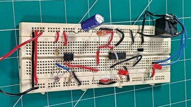
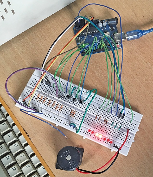
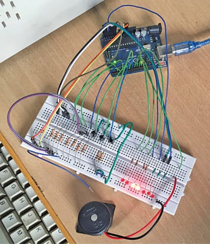
The writer’s prototype of window alarm annunciator based mostly on Arduino is proven in Fig. 1.
Circuit and Working
The circuit diagram of the window alarm annunciator is proven in Fig. 2. It’s constructed round Arduino Uno board (board1), seven LEDs (LED1 by LED7), three tactile switches (S1 by S3) and some discrete elements.
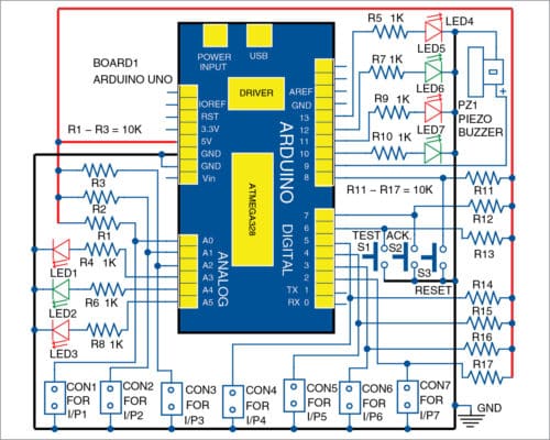
This annunciator has seven inputs related throughout connectors CON1 by CON7 for initiating the alarm by normally-open (NO) contacts.
There are additionally three enter switches (S1 by S3) for take a look at, acknowledge and reset. There are eight outputs, out of which seven are related with LEDs, akin to seven enter alarm contacts, whereas the eighth output is supplied for the buzzer.
(The buzzer will be changed with a hooter utilizing further circuitry)
All alarm inputs are designed for NO contacts. Other than digital pin 2 by pin 13 of Arduino, analogue pin A0 by pin A5 are additionally used as digital I/O pins to watch the seven completely different enter situations.
If any enter alarm contact is closed, the corresponding output LED will blink/flash at a quick price and the piezo buzzer can be activated to draw the eye of the consumer, or folks, close by. The alarm will be stopped by urgent the acknowledge pushbutton change (S2).
This can de-active the piezo buzzer and the LED will blink at a slower price. That’s, if alarm enter contact is opened, alarm sound will cease however the LED will proceed to flash at a sluggish price. When reset button (S3) is pressed, the LED will go off utterly.
Allow us to take an instance. Initially, all inputs are open, so all LEDs are off. If there may be downside with the primary machine, first enter I/P1 at CON1 will shut, LED1 will flash at a quick price and PZ1 will make an alarm sound.
When S2 is pressed, with I/P1 closed, PZ1 can be off however LED1 will keep on. When S2 is pressed, with I/P1 open, PZ1 can be off and LED1 will flash slowly till S3 is pressed momentarily.
Check pushbutton change S1 is supplied to check the LEDs and the buzzer. When S1 is pressed, all window alarm LEDs will glow steadily, and the buzzer can be activated. This can proceed until S1 is launched.
Arduino Code for Window Alarm Annunciator
The software program is written in Arduino programming language utilizing Arduino IDE model 1.8.5. Earlier than importing the given sketch/program to Arduino Uno, be sure that elapsed Millis library perform is out there in Arduino IDE (Sketch>Embrace libraries>Arduino libraries).
If not, obtain elapsedMillis-master folder from supply.efymag.com. Then, embrace the zip file by following the steps given beneath.
Sketch>Embrace libraries>Add. ZIP Library…>and browse the situation the place elapsed Millis file is saved. After including the above library perform, be sure that it seems within the record of library capabilities. Now, add Annunciator.ino sketch file to the board.
Obtain Supply Folder
PCB Design
A PCB structure of the window alarm annunciator is proven in Fig. 3 and its elements structure in Fig. 4. After assembling the circuit, enclose it in an appropriate field, together with Arduino Uno. Repair all LEDs on one facet of the cupboard and piezo buzzer on the opposite. Energy provide for the circuit is used by Arduino board and related by the USB port of the laptop computer/desktop.


Obtain PCB and Part Format PDFs: click on right here
Building and Testing
All inputs, I/P1 by I/P7, are potential-free exterior NO contacts with a typical floor rail. That’s, all inputs coming from the home equipment/machineries must be NO. Enter contacts ought to shut when issues like overload or short-circuit happen within the load of a number of home equipment/machineries.
For simple and fast testing, assemble the circuit on a breadboard, as per the given connection diagram. All inputs will be initiated, together with acknowledge, take a look at and reset inputs, by urgent the respective switches.
Warning!
Solely potential-free exterior NO contacts must be used as alarm contacts (CON1 by CON7) with a typical floor. In any other case, exterior voltage injected into the circuit will harm Arduino Uno.
If lengthy cables are used for alarm enter, EMI suppression circuits/optocoupler circuits must be added to forestall spurious operation or harm.
Enhancements for a Dependable and Versatile Window Alarm Annunciator
- Customizable Outputs: You should use the output pins to function different alert mechanisms, reminiscent of relays or a siren, to generate louder alarms.
- Distant Monitoring: Use an IoT module (such because the ESP8266) to ship notifications to a smartphone or distant system when the alarm is triggered.
- Energy Backup: Embrace a battery backup to supply steady operation throughout energy outages, growing reliability for dwelling or industrial safety.
- Person-Pleasant Enclosure: Create an enclosure that clearly labels the LEDs and buttons, making the system easy to grasp and use for anybody.
- Expandable Inputs: For those who’re monitoring quite a few factors, make the most of a multiplexer to reinforce the variety of inputs, permitting the system to accommodate extra sensors or connections.
P. Balasubramanian is a retired scientific officer from Nuclear Energy Corp. of India Ltd (NPCIL). His areas of curiosity embrace microcontrollers and energy electronics
This text was first revealed on 9 November 2019 and lately up to date in 2024.

