
Introduction
In India, many homes have primarily two sources of water to fill the rooftop water tank. These are underground storage tank and municipal water provide. Based mostly on the supply, the rooftop tank is crammed both with the municipal provide or with the underground storage tank manually. The rooftop tank is crammed with water from underground storage tank which the assistance of a water pump.
This guide approach of filling the tank requires loads of guide monitoring of the water stage contained in the tank and in addition improve the wastage of water. To scale back water wastage and to enhance the standard of life, this venture goals to fill the tank routinely with none human intervention.
This venture will decide the extent of water within the rooftop tank, verify for the supply of any provide to fill the tank, after which fill the tank to the specified stage utilizing any of the 2 out there supply. The filling of the tank by means of municipal provide is managed by means of a solenoid valve and the water pump is managed by means of a contactor. The choice making is completed by means of a microcontroller i.e., Arduino Nano and lots of analog digital units like BJT, MOSFETs, and diodes are additionally utilised.
Design
Methodology:
The working of the venture will be outlined utilizing two circumstances which can utilise totally different water supply based mostly on availability.
Case 1: Water stage is beneath 75% and municipal provide will not be out there.
On this case, water shall be crammed by means of the underground tank utilizing water pump until a most of 75% water stage is reached.
Case 2: Water stage is beneath 100% and municipal provide is out there.
On this case, water shall be crammed by means of the municipal provide to the tank’s full capability. A solenoid valve shall be used to cease filling the tank after the tank is totally crammed.
Mechanical Design:

The supply of municipal provide is detected by the 2 electrodes drilled into the pipe and linked to Arduino. The hole between the electrodes acts as a hindrance to the move of present (Resistance). When the availability is out there then the present begins flowing by means of the electrodes which then is detected by the Arduino (Microcontroller).
The move of water from the municipal provide is managed by means of a solenoid valve and the water pump is used to fill the water from underground storage tank to rooftop tank.
Two a method valves are used to stop reverse move of water. The 2 provide is merged to a single outlet by means of a T-connector.
Circuit Diagram:
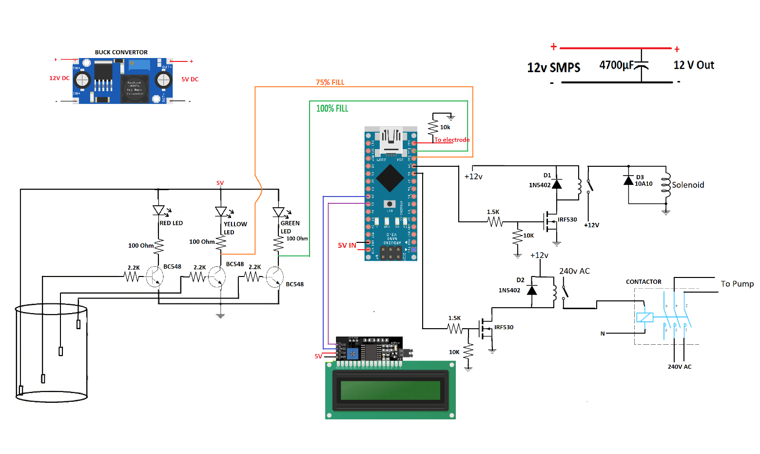
The water stage is set by the three BJTs appearing as a change. The bottom of the BJTs are linked to the electrodes dipped into the tank at totally different ranges (50%, 75% and 100%) by means of a resistor. When the water stage reaches an electrode then the corresponding BJT activates and thus the LED linked to the BJT additionally activates. The collector pins from the 2 BJT can be linked to the Digital pins of the arduino to additional outline the logic of the circuit.
A 16×2 LCD is linked to the arduino nano by means of I2C communication to show the standing of provide and water pump.
The solenoid valve is managed by way of a relay. The relay is managed by the IRF530 MOSFET. The gate pin of the mosfet is linked to the digital pin D9 of arduino nano by means of a resistor. A resistor is linked between gate of the MOSFET and floor which acts as a pull down resistor. A flyback diode is join in parallel to the coils of the relay to guard the MOSFET from excessive voltage created by collapsing magnetic fields.
The water pump will be instantly managed by means of the relay however as a consequence of excessive inrush present of the pump, the contacts of the relay can eaisly get broken. Therefore, we’re utilizing a contactor. A contactor is just like a relay however it’s operated with a 220V AC and has a much bigger and heavier steel contacts which may’t get broken eaisly. The contactor is managed by means of the identical relay-MOSFET system as defined above. The gate pin of the MOSFET is linked to digital pin D8 of arduino nano.
The arduino nano is powered with a 5V enter. The 5V achieved by means of a buck convertor linked to a 12V provide. A 4700uF capacitor is connect with the 12 provide to behave as a Low-Cross filter.
Arduino Code:


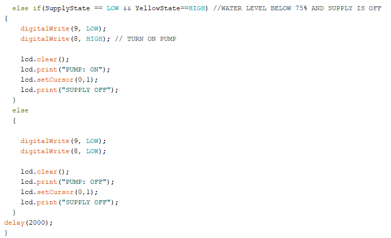
Within the Arduino code, the behaviour of {hardware} parts is outlined based mostly on the Methodology talked about eairlier.
The variables GreenState, YellowState information the state of the transistors linked to inexperienced and yellow LEDs. For the reason that output is 180 diploma section shift, ‘HIGH’ corresponds to transistor being off and ‘LOW’ correcponds for the transistor being on.
The info from these variable is additional used to outline if –else logic to regulate the solenoid and the water pump.
A 16×2 LCD is used to show the state of the 2 water sources. The LCD is being managed utilizing I2C communication. The libraries, Wire.h and LiquidCrystal_I2C.h is utilised for I2C communication to the LCD.
After every loop, a delay of 2000ms is added within the execution of the code.
Design Implementation
Mechanical Construct:
The mechanical a part of this venture is constructed utilizing ½ inch PVC pipe and its fittings.
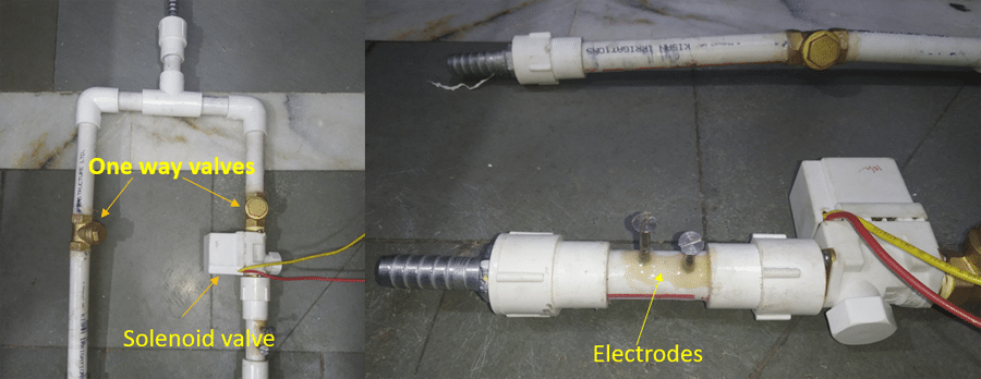
The next fittings are used:
- Elbow connector
- T- connector
- Feminine copper adapter
- Metal Hose nipple
Two steel nails are inserted into the PCV pipe to behave as electrode to detect the supply of municipal provide (As mentioned in Mechanical Design Part)
Circuit:
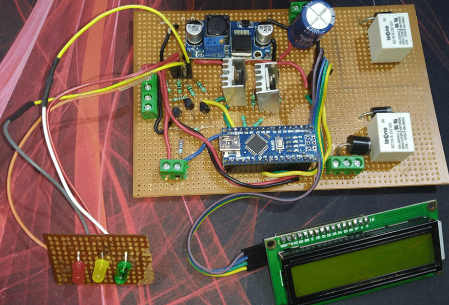
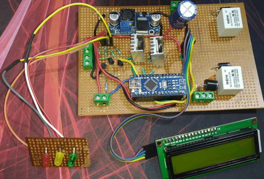
The whole circuit is soldered on a perfboard as per the circuit diagram. Terminal blocks are utilized to attach the 12v dc energy, stage probe, electrode and the solenoid.
The three LEDs are soldered on a separate perfboard as a way to mount it to the enclosure.
Warmth skins are added to the MOSFETs to dissipate warmth generated throughout MOSFET’s operation.
Full Digital Meeting:
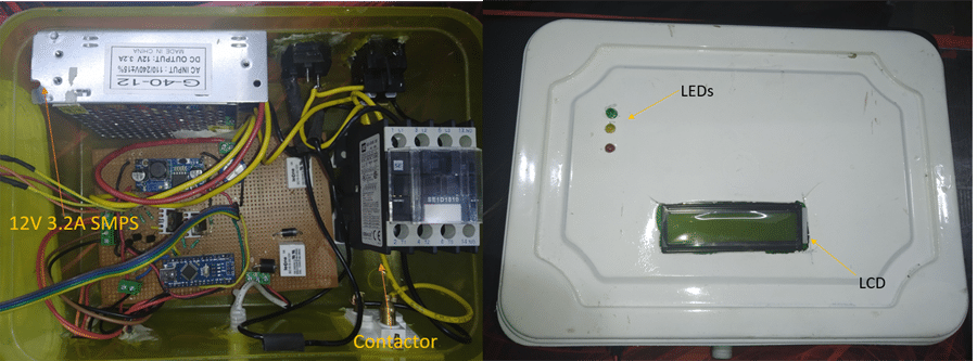
The circuit is enclosed inside a plastic enclosure with the lid getting used to mount the LCD and the LEDs. Together with the circuit, a 12V 3.3A SMPS and a Contactor can be enclosed contained in the enclosure.
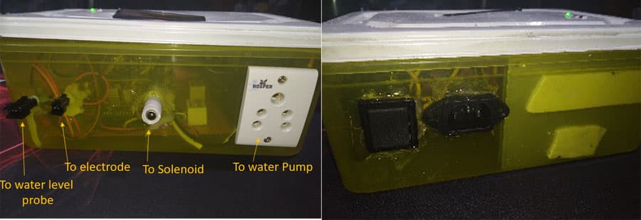
On the Sides of the enclosure, totally different connectors are mounted to attach deferent sensing components and units.
These connectors are:
- JST connectors to attach the water stage probe and the electrodes
- DC jack to attach Solenoid Valve
- 220v 3pin connector to attach Water Pump
- AC 220V 10A 3pin Panel Mount Plug Socket for enter 220V
- A ten A rated change
Full Meeting:
The mechanical half is mounted vertically on a small tank. And thru a small gap, the water stage probe is inserted within the tank.
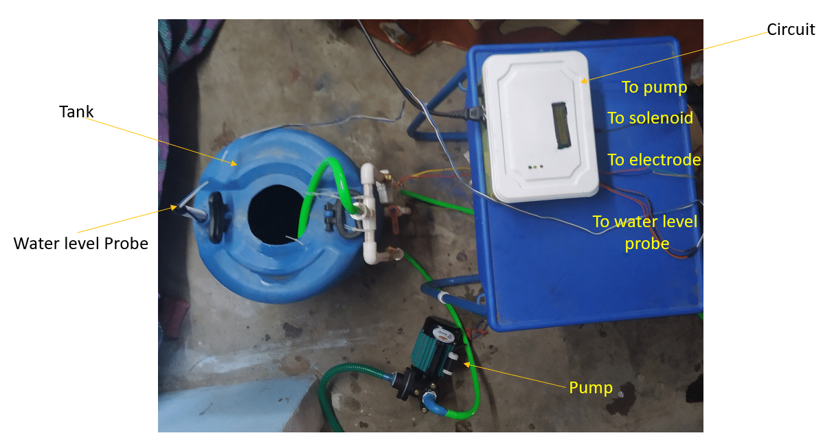
A 0.5 HP water pump is linked to our mechanical construct which shall be managed by means of the circuit.
Working:
Case 1: Water stage is beneath 75% and municipal provide will not be out there.

Case 2: Water stage is beneath 100% and municipal provide is out there.


Future Enhancements
- The water stage probe will be additional enhanced by including a grid of steel contacts to exactly measure the water stage.
- Water tends to fill within the provide checking electrode which typically tends to offer false knowledge concerning the availability of the availability. It may be improved by enhancing the mechanical design or through the use of a stress sensor as a substitute of steel electrodes.

