Electromagnetic interference can derail your PCB’s efficiency. EMI administration is not only a technical necessity however an indicator of outstanding PCB design.
Electromagnetic interference (EMI) poses a vital problem in printed circuit board (PCB) design. It happens when electrical indicators produce undesirable interactions by magnetic fields, doubtlessly disrupting digital circuit efficiency.
Managing EMI is a core accountability for PCB designers, who should be certain that designs adjust to regulatory noise limits.
To fulfill world EMI requirements, PCBs endure intensive testing, together with radiated immunity, performed emissions and immunity, electrostatic discharge (ESD), electromagnetic fields (EMF), and surge immunity. These assessments are costly, so designers should establish EMI points earlier than testing.

Relationship between electrical indicators and magnetic fields
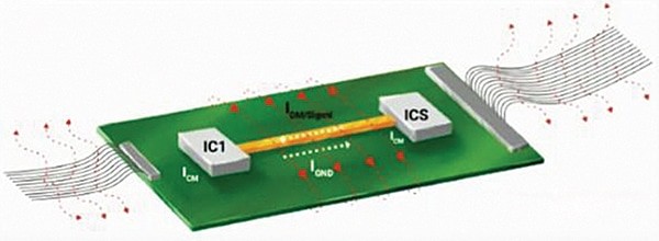
Maxwell’s equations encapsulate the basic relationship between electrical indicators and magnetic fields, which describe how various electrical fields can generate magnetic fields and vice versa. When present flows by a conductor, it generates a magnetic discipline round it. Excessive-frequency indicators or massive present spikes can produce robust electromagnetic fields that will intervene with close by digital elements, resulting in EMI.
PCB stack-up and layer configuration
A well-planned PCB stack-up can considerably scale back EMI. A typical multilayer PCB consists of sign layers, energy planes, and floor planes. Correct placement and configuration of those layers are vital.
Sign layers. Excessive-speed sign traces needs to be routed on inner layers sandwiched between floor planes. This association helps include the electromagnetic fields throughout the PCB and reduces radiated EMI.
Energy and floor layers. Energy planes needs to be positioned adjoining to floor planes to create low-inductance paths for return currents. This configuration additionally supplies good decoupling and reduces noise.

Hint routing. Hold high-speed traces brief and direct. Use differential pairs for high-speed indicators to minimise EMI by cancelling out magnetic fields generated by every hint.
Partitioning PCB into digital and analogue sections
Please register to view this text or log in under. Tip: Please subscribe to EFY Prime to learn the Prime articles.

