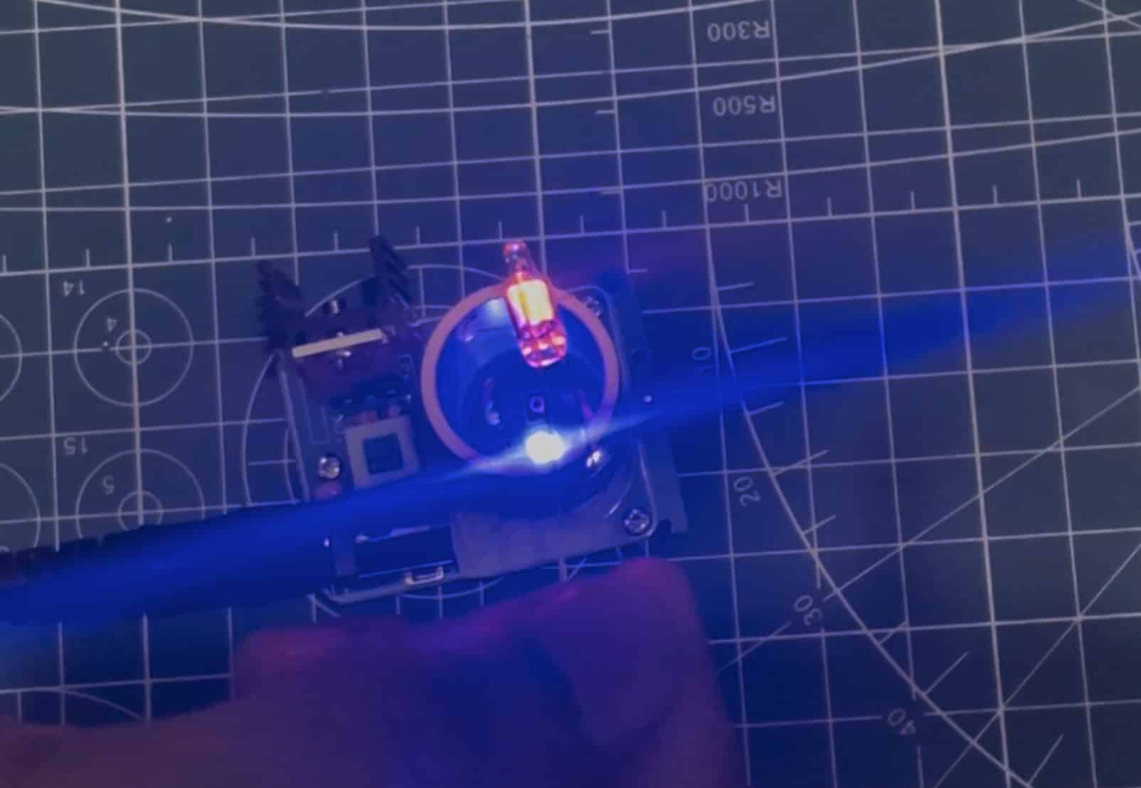
The Tesla coil is a high-frequency resonant transformer circuit able to producing high-voltage, low-current electrical energy. This fascinating invention, attributed to Nikola Tesla, is commonly used for wi-fi energy switch demonstrations and lighting fluorescent bulbs with out bodily connections.
On this article, we are going to discover the design means of a mini Tesla coil, protecting its parts, circuit particulars, PCB design, and the testing process.
The Tesla coil works on the precept of electromagnetic induction and resonance. By making a resonant LC (inductor-capacitor) circuit, it steps up the voltage to extraordinarily excessive ranges, producing a high-frequency alternating present.
Additionally Examine: LC Resonant Frequency Calculator [Free]
This high-frequency AC generates an oscillating electromagnetic subject, enabling wi-fi energy switch to close by objects like fluorescent bulbs.
Invoice of Supplies (BOM)
The next parts are required to design a Tesla coil:
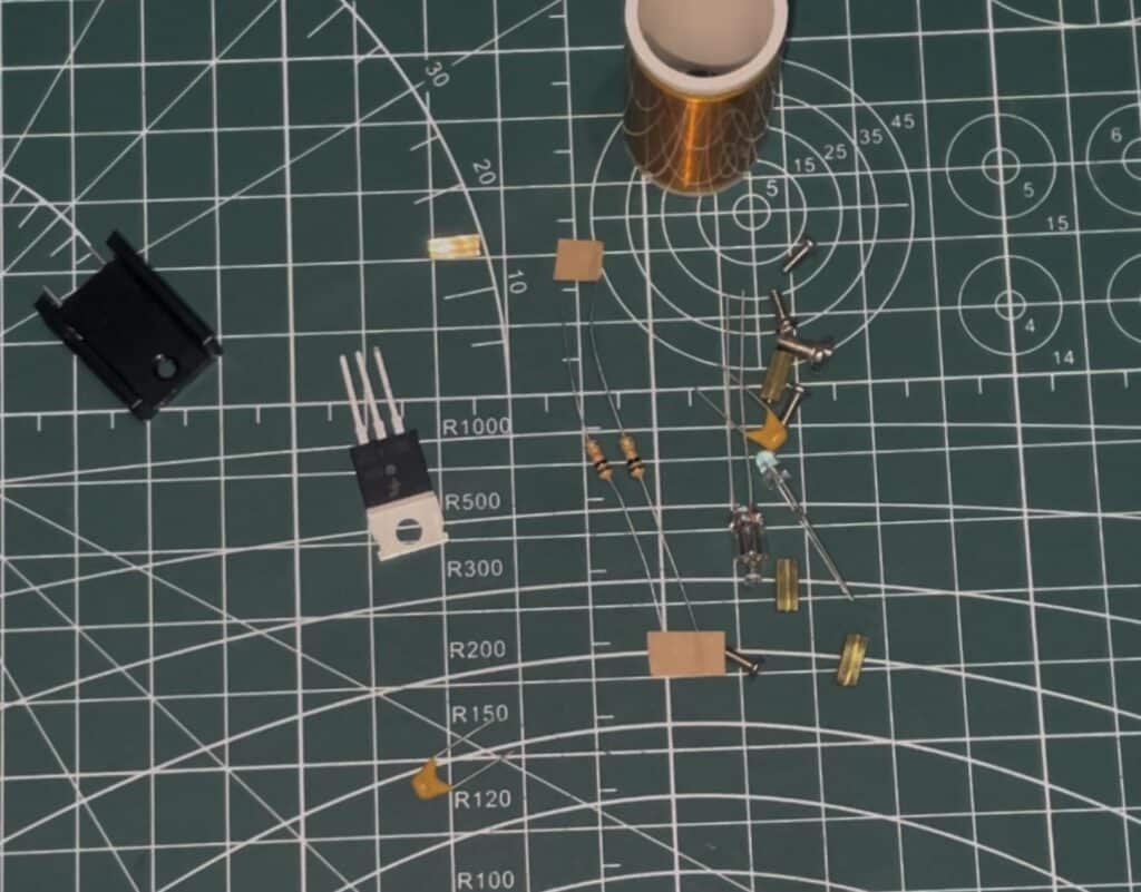
- Major Coil and Secondary Coil:
- The first coil consists of some turns (3–5) of thicker copper wire. This coil generates the magnetic subject.
- The secondary coil is wound with finely enamelled copper wire (~1000 turns) to realize excessive voltage.
- Capacitor:
- A 0.01 µF capacitor varieties an LC circuit with the first coil, enabling resonance.
- Transistor:
- The transistor acts as a change, driving the first coil with pulsed DC.
- Resistor:
- The resistor limits the bottom present of the transistor to stop injury.
- Energy Provide:
- A 9–12V DC energy supply provides vitality to the circuit
Tesla Coil Circuit Diagram
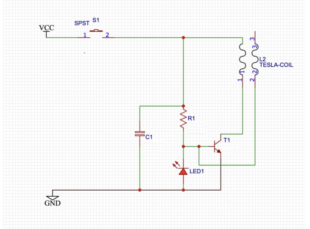
PCB Design of Tesla Coil and Wi-fi Energy Bulb
To create a dependable Tesla coil, the next PCB design issues are essential:
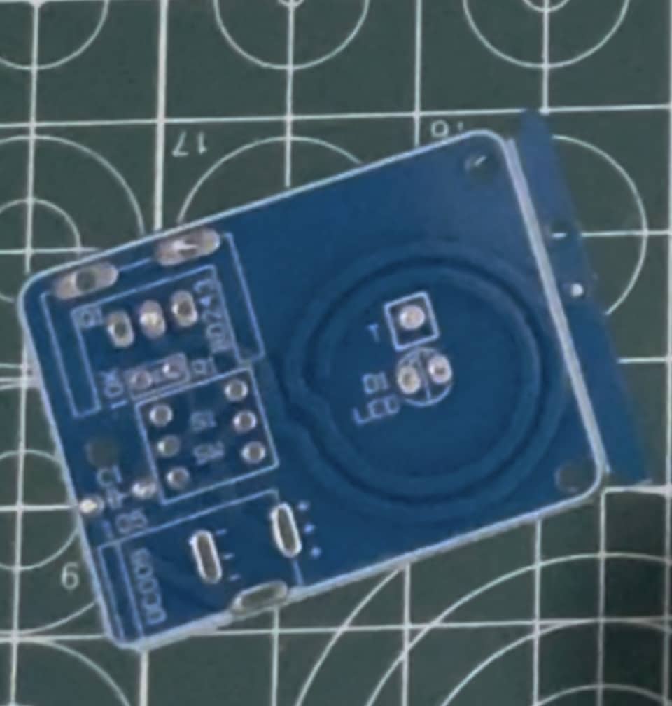
- Element Placement:
- Place the capacitor and resistor near the transistor to attenuate stray inductance.
- Maintain the first coil connection quick to scale back losses.
- Copper Traces:
- Use thicker traces for high-current paths, particularly for the first coil circuit.
- Insulation:
- Guarantee correct insulation and spacing across the secondary coil to deal with excessive voltages.
Soldering Tesla Coil and Wi-fi Energy Bulb
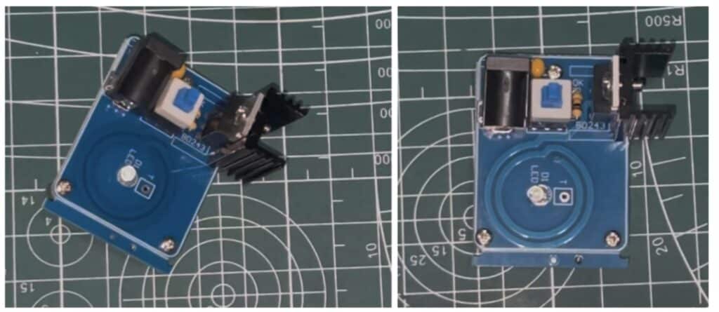
- Solder Passive Elements:
- Start by soldering the resistor (22 kΩ) and the capacitor (0.01 µF).
- Make sure the polarity of the capacitor is appropriate if it’s polarized.
- Solder the Transistor:
- Place the transistor on the PCB, making certain the right orientation of the bottom, collector, and emitter pins.
- Solder the Major Coil:
- Join the thicker copper wire (3–5 turns) to the designated PCB pads.
- Solder the Secondary Coil:
- Connect the secondary coil’s base wire to the PCB pad and depart the opposite finish free for wi-fi energy switch.
- Solder the Energy Connections:
- Join the facility provide terminals and the change.
Testing Tesla Coil and Wi-fi Energy Bulb
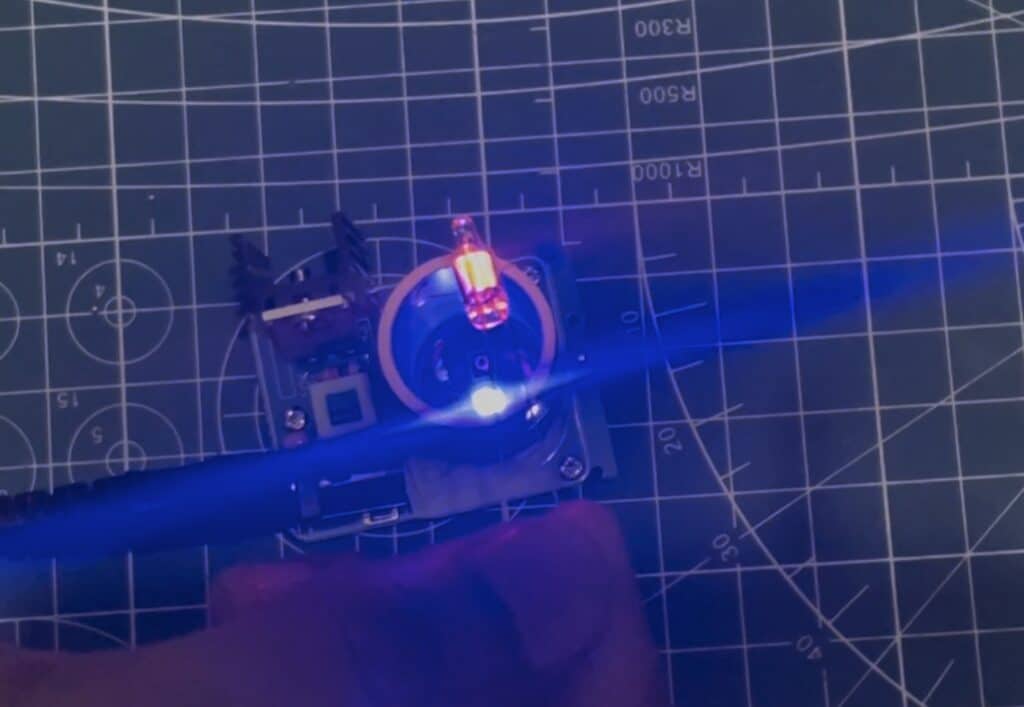
Now energy the gadget with a 12V 1-2A DC adapter after which activate the change and there you go, Deliver the fluorescent bulb or AC bulb close to the coil and it’ll glow up wirelessly as quickly because it comes close to.

