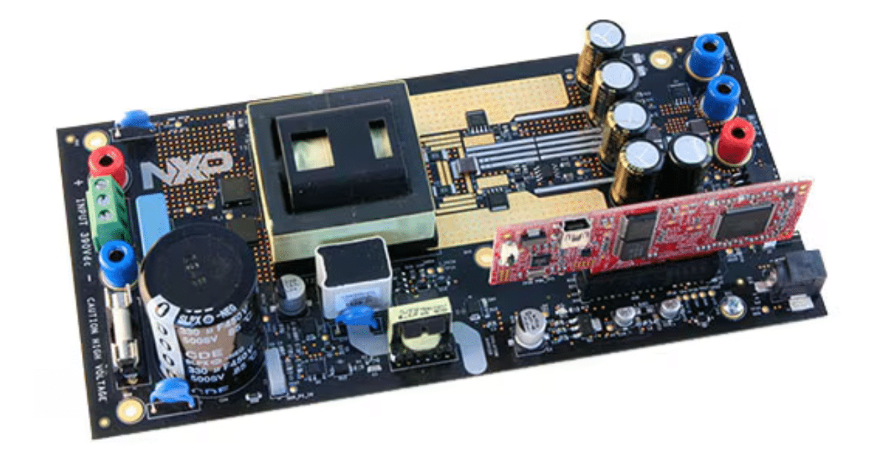
The converter board system converts 390 V DC to 12 V/21 A, attaining over 96% effectivity. It’s designed for secure use in labs and handles excessive voltages properly.
The high-voltage resonant converter board (HVP-LLC) from NXP Semiconductors, paired with the HVP-KV46F150 controller card, types a system for a 250-W energy provide with a 390 V DC enter and a 12 V/21 A output. This setup incorporates GaN low-loss switches and a digitally-controlled synchronous rectifier, attaining efficiencies over 96% throughout a broad load spectrum. The system includes the controller card and the principle board.
The board set operates with excessive voltages that pose dangers {of electrical} shock, hearth hazards, or private damage if not correctly managed. Use this board with warning and implement security measures to forestall hurt or harm. It’s appropriate just for people accustomed to high-voltage electrical techniques and needs to be used solely in a laboratory atmosphere.
The high-voltage energy stage needs to be powered by a current-limited laboratory energy provide for secure operation. If a non-isolated energy provide is used, one should concentrate on potential variations in floor potentials between the facility stage and the oscilloscope, until the oscilloscope is floating. It’s suggested to train warning, as each probe grounds and a floating oscilloscope can carry harmful voltages.
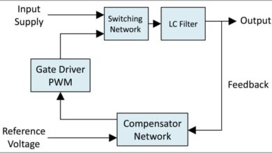
The necessity to improve the facility density of switched-mode energy provides (SMPS) compels designers to go for larger switching frequencies. Nonetheless, this improve in frequency results in better switching losses in Pulse Width-Modulated (PWM) converters, lowering total effectivity. Though larger frequencies permit for smaller passive elements, saving area, this profit is commonly offset by the necessity for bigger warmth sinks or pressured cooling techniques. Consequently, SMPS designers are regularly trying to find methods to scale back these switching losses. One efficient strategy to deal with these points is the usage of resonant converter topologies. Resonant converters incorporate a resonant circuit throughout the conversion pathway.
The LLC resonant topology presents a number of advantages over different resonant topologies. Most switched-mode energy provides incorporate a transformer to attain galvanic isolation or to regulate enter/output voltage ranges. The inclusion of a transformer within the LLC resonant topology offers extra benefits.
The primary board encompasses a vary of specs designed to accommodate varied wants. It helps an enter voltage of 330-390 V DC and might ship an output energy of as much as 250 W. The output voltage is about at 12 V, with a capability to deal with an output present of as much as 21 A. It operates at a switching frequency vary of 75-300 kHz and incorporates GaN low-loss switches. The board is supplied with passive cooling, a digitally-controlled synchronous rectifier, and strengthened galvanic isolation for enhanced security. It additionally consists of over-current and over-voltage safety mechanisms. For connectivity and monitoring, the board options an SM-bus interface, a serial interface, and analog sensing for output voltage, output present, and resonant circuit present. Moreover, it helps a number of MCU playing cards and features a load change for step-response tuning.
NXP has examined this reference design. It comes with a invoice of supplies (BOM), schematics, meeting drawing, printed circuit board (PCB) structure, and extra. The corporate’s web site has extra knowledge concerning the reference design. To learn extra about this reference design, click on right here.

