Hearth has at all times been necessary to human progress, but it could be dangerous if not dealt with. Whereas firefighters fight large flames, early intervention at dwelling can typically keep away from severe accidents. This venture describes the creation of a prototype fire-extinguishing robotic that intends to fight home fires of their early phases.

Hearth Preventing Robotic – Circuit and Working
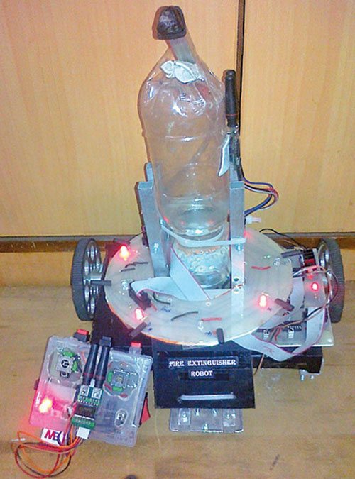
This fireplace extinguishing robotic is a prototype (Fig. 1) of the particular one. Sensors used listed here are easy infrared (IR) photodiodes that detect IR rays popping out of the fireplace. The sensor board mounted on prime of the robotic’s chassis is round in order that it offers the robotic an all-round detection view of 360°.
Sensors are equally spaced at 45° every. These act because the eyes of the robotic.
Within the precise robotic, using fireplace sensors or IR cameras is really useful. However these are too costly and therefore IR photodiodes have been used as an alternative within the prototype.
The pump used right here symbolizes the fireplace extinguishing mechanism and is used as an alternative within the prototype.
Additionally, the physique used shouldn’t be fire-proof. The precise robotic should use fire-proof materials for correct and higher functioning for environment friendly outcomes.
IR Waves:
Wavelengths longer than seen and as much as 1mm are termed IR waves. IR radiation may be felt as radiant warmth, for instance, while you stand in entrance of a hearth.
The sunshine emitted by a burning supply includes IR waves, so through the use of IR photodiodes as sensors, we will detect a hearth. This precept has been used within the design of the sensor board.
DC Water Pump:
A DC water pump is used for extinguishing fires. It pumps out water saved in a bottle. Every other appropriate water pump may also be used.
RF Module:
A pair of 433MHz RF transmitter-receiver modules is used. It permits the transmission and reception of serial information and not using a bodily connection. The frequency of an RF sign is inversely proportional to the wavelength of the sector.
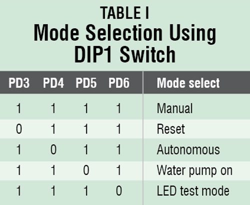
The robotic may be made to work in handbook in addition to in autonomous mode. (Guide mode was examined at EFY Lab.) Completely different modes of operation are given in Desk I.
Hearth Extinguishing Robotic Works in Three Phases
Stage 1: Hearth Detection (Autonomous Mode)
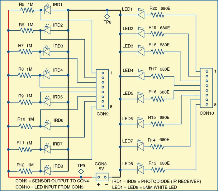
IR photodiodes are linked in reverse bias as proven within the circuit diagram of the sensor module (Fig. 3). Anodes are generally linked to the bottom and cathodes are linked to the 5V by way of resistors of 1MΩ every.
The voltage throughout the photodiode is given as enter to ADC pins (PA0 by PA7) of ATmega16.
When IR waves fall on the IR photodiode, its resistance decreases from 650kΩ to 150kΩ, decreasing the voltage throughout the photodiode, thus altering the enter voltage on the ADC pin.
By correct quantisation, the presence and absence of the flame may be distinguished.
Equally, eight IR photodiodes mounted circularly on the sensor board assist detect the fireplace; the corresponding LED glows if the fireplace is detected.
The cone of detection of the IR photodiode is giant, thus lowering the decision of the system. This downside may be solved by correctly shielding IR photodiodes.
The code to detect the presence of fireplace utilizing the ADC is as follows:
{
unsigned char v;
v= read_adc(0);
if(v>=0 && v <=128) //Shops the digital worth of the analog voltage at ADC 0 fire_detected ( ); if(v>128 && v<=255)
fire_not_detected( );
}
Stage 2: Extinguishing Hearth
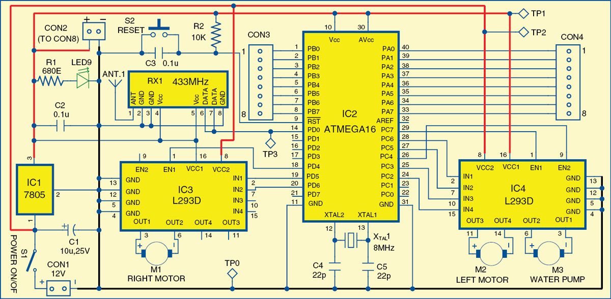
Fixed suggestions from sensors is fed to the primary module by CON4, and therefore the place of the fireplace with respect to the robotic is set.
The principle module contains an ATmega16 microcontroller, two L293D motor driver ICs to drive motors, a water pump and an RF receiver RX1. The circuit diagram of the primary module is proven in Fig. 3.
The fundamental perform of the algorithm is to orient the entrance sensor in entrance of the fireplace in order that the nozzle of the pump comes instantly above the fireplace supply. When that is achieved, the pump begins and extinguishes the fireplace.
The robotic strikes with the assistance of two motors, whose sense of rotation is managed by the controller, relying on the suggestions from the sensor.
Stage 3: RF Communication and Guide Management (Guide Mode)
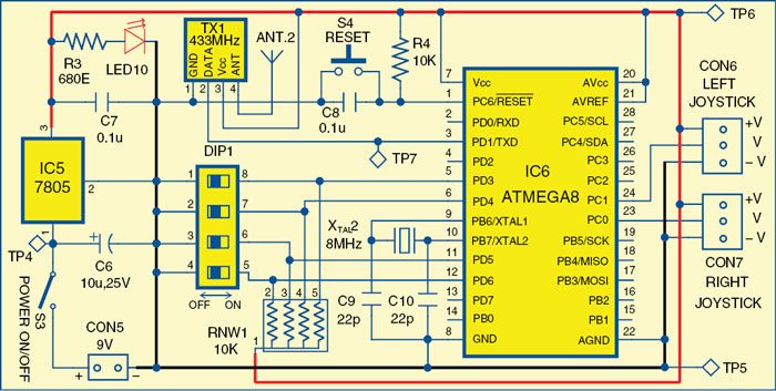
The robotic is managed by the operator with the assistance of a wi-fi distant (circuit diagram is proven in Fig. 4) that makes use of an RF module for speaking with the robotic.
Switches, push buttons, and joysticks are offered on the distant that controls numerous duties similar to autonomous mode choice, resetting and beginning the pump.
For every command, the distant sends a particular character that’s obtained by the robotic and the corresponding operation is carried out.
Specimen code for autonomous mode is given as under:
For distant (transmitter):
if(check_bit(&PIND,4)==0)
{
i=’h’; //auto mode
printf(“%c”,i);
}
For robotic (receiver):
whereas(1)
{
scanf(“%c”,&ii);
_delay_ms(10);
swap(ii)
{
case ‘h’: //auto mode
autonomous();
break;
Software program and Programming Hearth Extinguishing Robotic
Programming of the AVR is completed utilizing embedded C language. It’s just like C language however contains all functionalities of C in addition to entry to AVR pins, peripherals and controls. C code is transformed to hex code utilizing WinAVR.
Hex codes generated are burnt into MCUs for the primary module (robotic) and the distant module. The working of this system is defined as feedback in the primary module (robotic) and distant module supply codes.
This system jumps to the primary perform the place the thing code begins. On the distant module, a DIP (DIP1) swap is interfaced utilizing which you’ll choose the working mode (autonomous or handbook), swap off the water pump, reset all settings or LED indicators take a look at mode as given in Desk I.
Required Instruments and Software program
WinAVR
WinAVR is a set of executable, open-source software program growth instruments for the Atmel AVR sequence. It contains GNU GCC compiler for C and C++, Programmer’s Notepad, Makefile, and so forth.
Programmer’s Notepad (PN)
It is a supply editor with some IDE options. PN can name any command-line instrument and seize its output. It’s best for calling the make utility, which executes the make file, which, in flip, calls the compiler, linker and different utilities used to construct your software program.
Makefile
WinAVR now contains MFile utility, an automated make file generator for AVR GCC, which may run on numerous platforms together with Home windows, FreeBSD and Linux. You should use this utility to shortly generate make recordsdata in your venture primarily based on some easy menu enter.
Obtain Supply Code: Click on right here
PCB Design
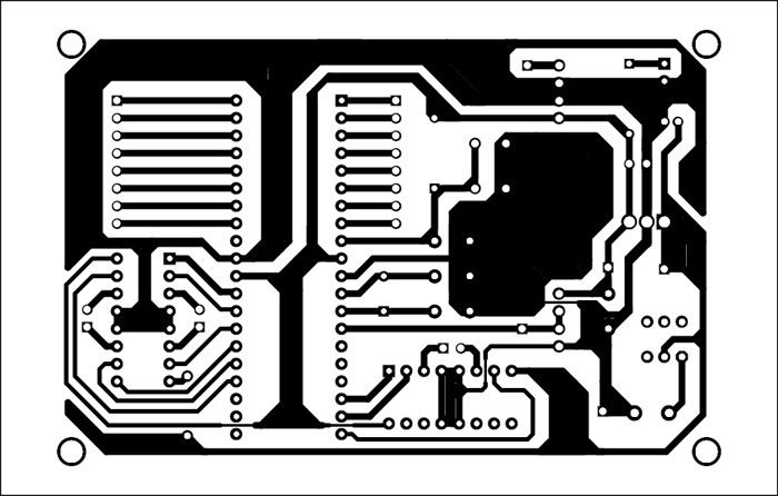
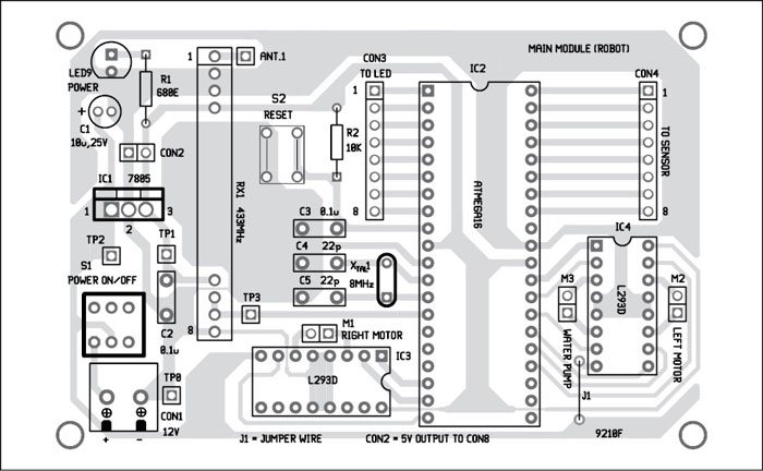
A single-side PCB of the primary module is proven in Fig. 7 and its element structure in Fig. 8.
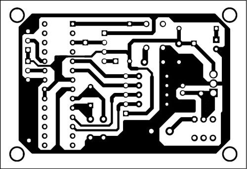
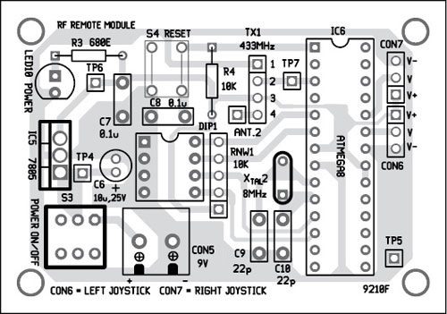
A single-side PCB of the RF distant module is proven in Fig. 9 and its element structure in Fig. 10.
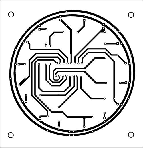
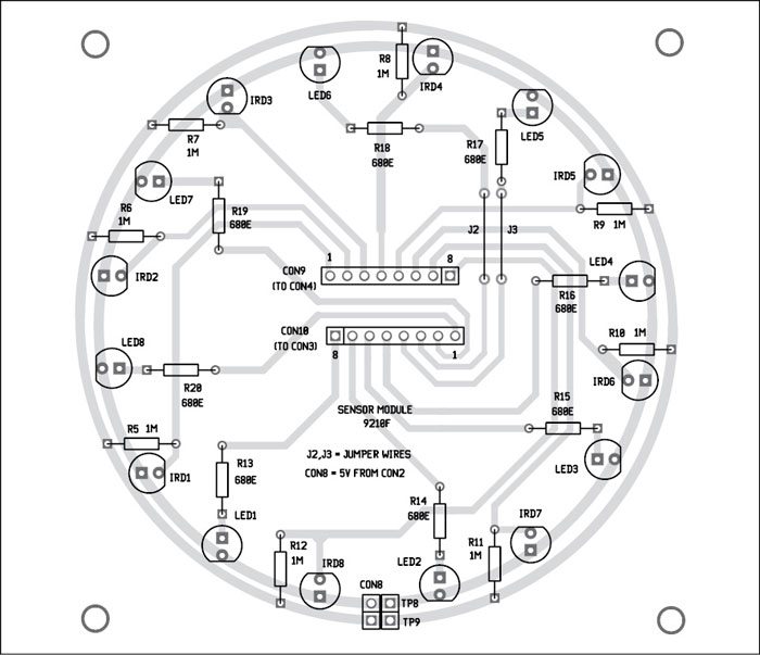
A single-side PCB of the sensor module is proven in Fig. 11 and its element structure in Fig. 12.
Obtain PCB and Part Format PDFs: Click on right here
You can too assemble the circuit on a general-purpose PCB. Earlier than mounting the MCUs on PCBs, burn respective codes into MCUs utilizing an appropriate programmer board.
Testing Hearth Preventing Robotic
After mounting all elements on PCBs, swap on the ability provides of respective models.
On the important module (robotic), initially, 4 LED indicators glow on even pins of PORTB of IC2 by default, and the robotic waits for the sign from the RF distant. You can too take a look at all of the LEDs by pulling port PD6 of IC6 low by the DIP1 swap.
For handbook mode, there are two joysticks linked to the ADC channels of the controller (PC0 and PC1) on the distant module. By utilizing the joystick, robotic actions may be managed.
Transfer your robotic in direction of the fireplace supply. Pull PD5 of IC6 to low by the DIP1 swap to change on the water pump.
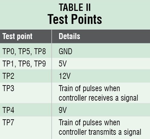
For troubleshooting the circuit, test to make sure voltages at numerous take a look at factors are as per Desk II.
Functions
1. By changing IR picture sensors with the thermal image-processing digicam, the pump with a hearth extinguishing mechanism and by making the physique of the robotic fire-proof, it may be used for fireplace extinguishing functions. It may also be used to help firefighters, thus serving to them attain inaccessible locations to avoid wasting extra lives.
2. Growing the variety of sensors will enhance the decision and accuracy of the system additional.
3. In autonomous mode, it could actually detect a hearth, if any, and extinguish it with none help.
4. The RF module makes it attainable for the operator to regulate the robotic manually from a distance, thus permitting surveillance facility.
Limitations
IR photodiodes additionally react to solar rays, identical to fireplace, since these too include IR waves, thus permitting the robotic to make false judgments.
Nonetheless, the impact of daylight and different components shouldn’t be vital if we use higher sensors (that are much more pricey).
Potential Upgrades for Enhanced Performance
- Enhanced Sensors: Use flame-specific sensors for extra exact detection.
- Warmth-resistant Supplies: Warmth-resistant supplies increase sturdiness below precise fireplace circumstances.
- Superior Navigation: Use GPS or impediment detection to enhance motion in tough terrain.
- Battery Administration: Add a battery indication or automated charging for extended use.
This fireplace-extinguishing robotic is a working prototype that shows a cost-effective, automated methodology for correctly coping with minor residential fires. It may be additional personalized to offer extra complicated options for industrial or industrial use.
Different Hearth Safety Initiatives
Amol Gulhane has a B.Tech (electronics and telecommunication) from the Faculty of Engineering Pune and is co-founder of Robolab Applied sciences.
This text was first revealed on 8 April 2017 and not too long ago up to date in 2025.

