
A easy, low-cost machine can successfully alert owners or occupants if a parked automobile is moved or tampered with. This hardwired detector encompasses a foremost circuit with a buzzer alarm put in inside the home, whereas a sensor is mounted on the automobile being protected.
The sensor must be positioned on the automobile in a location shielded from warmth, rainwater, mud, and filth. Its leads have to be routed to an accessible level outdoors the automobile for simple connection to the wires coming from the principle circuit.
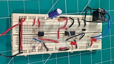
For constant safety, the sensor leads should stay related to the principle circuit each time the automobile is parked. Any disconnection, chopping, or shorting of the wires triggers the alarm and prompts the LED indicator. The detector is powered by an exterior 12V DC adaptor, with a 9V dry cell offering backup throughout energy failures. Fig. 1 shows the creator’s prototype of the detector.

Circuit and dealing
Fig. 2 reveals the circuit diagram of the automobile theft detector. The system is constructed round quad op-amp LM324 (IC1), quad 2-input NAND gate IC 7400 (IC2), and some different elements.
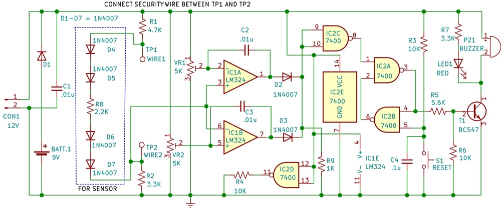
The quad op-amp IC LM324 (IC1) features as a voltage comparator. The IC1A comparator detects increased voltage output from the sensor (within the dotted field) when the connecting wires (between TP1 and TP2) are short-circuited or related whereas somebody makes an attempt to tamper with the automobile.
The IC1B comparator detects decrease voltage when the sensor wires are minimize or grow to be open-circuited. Potentiometers VR1 and VR2 present reference voltages for comparators IC1A and IC1B. Below regular circumstances, each comparators produce logic low outputs. Nonetheless, throughout voltage disturbances, the output of both comparator turns into logic excessive and provoke the alarm.
| Components Listing |
| Semiconductors: IC1 (IC1A, IC1B, IC1E) – LM324 quad op-amp IC2 (IC2A-IC2E) – 74C00 quad NAND gate T1 – BC547 NPN transistor D1-D7 – 1N4007 rectifier diode LED1 – 5mm LED purple color Resistors (all 1/4-watt, ±5% carbon): Capacitors: Miscellaneous: |
Development and testing
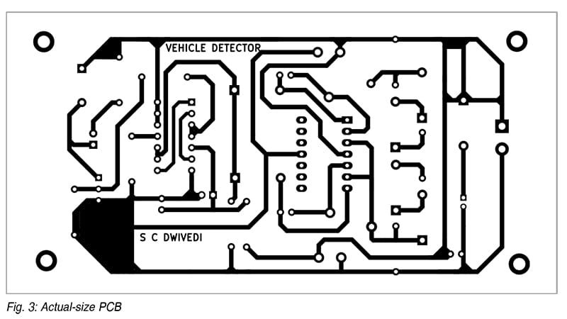
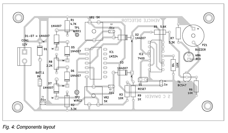
An actual-size, single-sided PCB format for the circuit is proven in Fig. 3, and its part format in Fig. 4. Alternatively, the circuit will be assembled as per Fig. 2 on a multipurpose board.
As soon as assembled, the mounted board must be enclosed in an appropriate enclosure with openings for the buzzer and LED indicator. A PVC electrical field, available at low price, is an effective choice. The sensor circuit will be soldered onto a strip of multipurpose board with sturdy results in join the principle circuit wires.
For testing, join the sensor (inside dotted traces within the circuit diagram) to the principle circuit PCB. Energy the circuit utilizing a 12V DC adaptor and a 9V backup battery.
Throughout calibration
- Modify potentiometer VR1 to three.85V and VR2 to 2.25V
• Join the safety wire loop between TP1 and TP2
• Open, quick and reverse; guarantee buzzer PZ1 and LED1 activate
• Press push button S1 momentarily to show off the buzzer and LED after connecting the safety loop between TP1 and TP2
• Repeat the checks utilizing a 9V battery, disconnecting the 12V DC adaptor
After passable testing, insulate and seal the sensor circuit in a small tube with epoxy compound, leaving solely the thick leads uncovered for exterior connection. The inner circuit of the sensor shouldn’t be seen to anybody.
Mount the sensor on the automobile and join it to the alarm circuit utilizing an appropriate size of weather-resistant twin-core cable. The connection close to the automobile will be achieved with crocodile clips, an auto wiring plug and socket, or another connector sort, based mostly on consumer desire.
The way it protects your automobile from theft
The primary circuit, together with the assembled PCB, ought to stay inside the home. The automobile to be protected must be fastened with sensor and twin wire and related between TP1 and TP2. If somebody makes an attempt to steal the automobile, the wire will break, triggering the buzzer to alert the consumer.
Warning
The 12V energy provide adaptor have to be of the mains-isolated sort, both step-down transformer and rectifier-based or SMPS sort. Non-isolated energy provides with capacitors or resistors for voltage discount must not ever be used, as this might result in electrical shock or electrocution when connecting or disconnecting wires to the automobile sensor.
To make sure trouble-free operation, the connecting wires must be laid rigorously in order that they aren’t disturbed by close by individuals, kids, or animals.
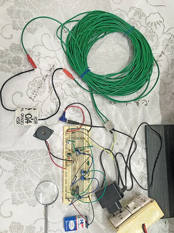
The machine has been examined with a 20-metre-long, 1mm dia, single-core cable (two wires), as proven within the picture. Nonetheless, such a thick cable is pointless. It is strongly recommended to make use of a twin-core copper flat cable (23/0052, 1100V grade).
EFY notice. It could be higher to assemble D4, D5, R8, D6, and D7 on a zero PCB reasonably than a PCB proven in Fig. 4. This meeting features as a sensor. Repair it within the automobile and join the 2 ends of the sensor wires (from the automobile) to the terminals TP1 and TP2 of the principle circuit utilizing two-core lengthy wires.
Modification
If a louder hooter is required, a 12V sugar dice relay with a freewheeling diode will be related in parallel to the present buzzer. The hooter can then be related via the relay’s usually open (NO) contact, powered by the 12V provide.
P. Balasubramanian is a retired scientific officer from the Nuclear Energy Company of India Ltd (NPCIL). His areas of curiosity embrace microcontrollers and energy electronics.

