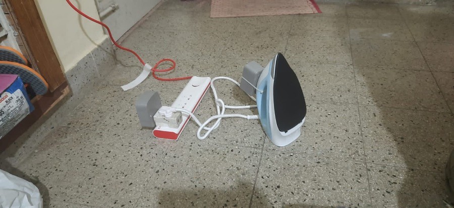

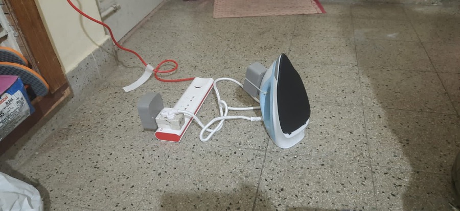
Throughout ironing the garments there’s a risk for the fabric to get burnt as a result of ironbox saved over the fabric unattended when attending any telephone calls or partaking in some other actions. To beat this concern we’ve got proposed an answer to robotically management the ironbox wirelessly, when unattended via deatacheable movement sensor. The distinctiveness of the system is it has a wi-fi management unit and a deatacheable sensing unit which could possibly be appropriate for various kinds of ironbox. Throughout ironing, the accelerometer and gyroscope sensor is used to detect the movement and place (vertical or horizontal) of the iron field, respectively and ship the info to the wi-fi management unit. The iron field is switched on solely when it’s in movement and positioned in vertical place,or in any other case it would switched off via the wi-fi management unit.
System design
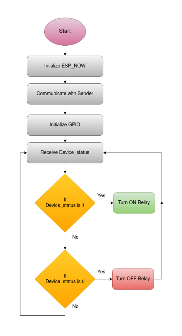
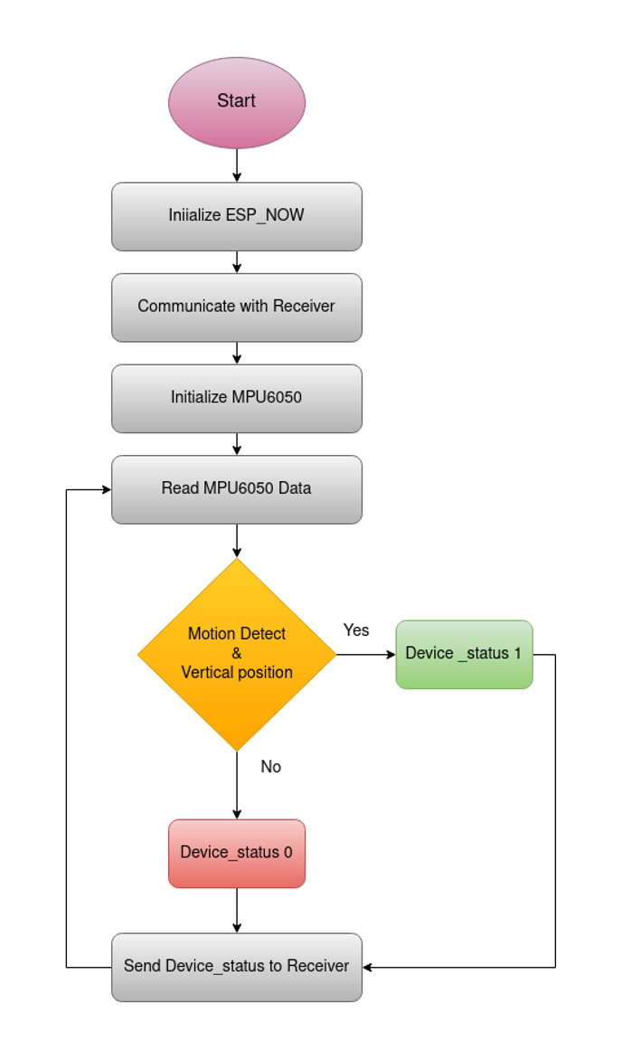
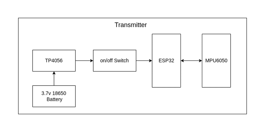
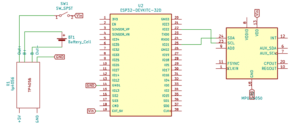
This venture is split into two part one is Sensing half one other one is Triggering half.The sensing half is named as Transmitter and Triggering half is named as Receiver. Fig.2. and Fig.3. reveals Block diagram of the Transmitter half and Receiver half. The Transmitter system makes use of MPU6050 as sensor to get the ironbox motion and it could detect x-axis, y-axis, z-axis. This sensor is I2C compatable and the info is acquired and processed utilizing the ESP32 microcontroller. The ESP32 additional course of the info and ship it to the Receiver half utilizing ESP-NOW protocol. The Receiver half will obtain the command if the command is legitimate (eg. 0 or 1), based mostly on the command receiver half will set off the relay.ESP32 microcontroller transceiver is used for getting legitimate instructions and to do actuation via relay drive circuitry. The Transmitter system makes use of 3.7 V Lithium ion rechargeable battery and it’s charged via TP4056 charging module. The charging module is linked with a 5 V USB charger. And Receiver system makes use of 230v AC to 5v DC converter, 5v relay module is used to drive the ironbox. Every time a sound command is acquired ESP32 triggers a HIGH or LOW sign to the GPIO pins linked with relay with respect to the command and relay actuates ironbox linked.

| Reference | Amount | Worth/Mannequin | Half description |
| U1 | 1 | TP4056 | TP4056 on a breakout board |
| BT1 | 1 | Battery Cell | 18650 3.7 V Lithium-ion rechargeable battery |
| SW1 | 1 | SW_SPST | Swap for enter energy |
| U2 | 1 | ESP32 DEVKITC-32D | ESP32 improvement board |
| U3 | 1 | MPU6050 | MPU6050 3 axis gyroscope and accelerometer |
Desk.1. Half Checklist for Transmitter
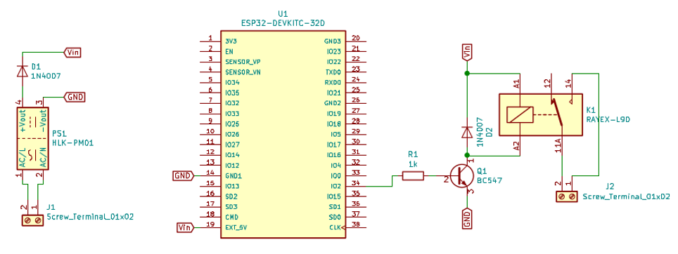
| Reference | Amount | Worth/Mannequin | Half description |
| J1,J2 | 2 | Screw_terminal_01x02 | Screw terminal block for Enter and Output |
| PS1 | 1 | HLK-PM01 | 5v Ac to Dc Energy provide |
| D1,D2 | 2 | 1N4007 | Normal objective diode |
| R1 | 1 | 1KOhm | ¼ Watt via gap resistor |
| Q1 | 1 | BC547 | NPN Transistor |
| U1 | 1 | ESP32 DEVKITC-32D | ESP32 improvement board |
| K1 | 1 | RAYEX-L90 | 30-amps T-type Relay |
Desk.2. Half Checklist for Receiver
MPU6050
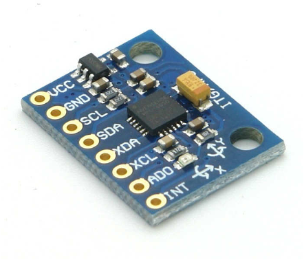
MPU6050 sensor module is full 6-axis Movement Monitoring Gadget. It combines 3-axis Gyroscope, 3-axis Accelerometer and Digital Movement Processor all in small package deal. Additionally, it has extra function of on-chip Temperature sensor. It has I2C bus interface to speak with the microcontrollers.
3-Axis Gyroscope
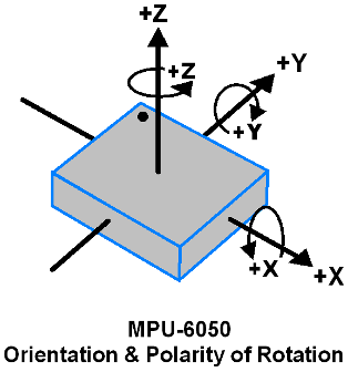
The MPU6050 include 3-axis Gyroscope with Micro Electro Mechanical System(MEMS) know-how. It’s used to detect rotational velocity alongside the X, Y, Z axes as proven in beneath determine. When the gyros are rotated about any of the sense axes, the Coriolis Impact causes a vibration that’s detected by a MEM inside MPU6050. The ensuing sign is amplified, demodulated, and filtered to provide a voltage that’s proportional to the angular fee. This voltage is digitized utilizing 16-bit ADC to pattern every axis. The total-scale vary of output are +/- 250, +/- 500, +/- 1000, +/- 2000. It measures the angular velocity alongside every axis in diploma per second unit.
3-Axis Accelerometer
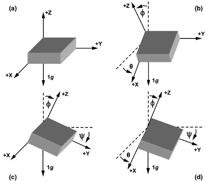
The MPU6050 consist 3-axis Accelerometer with Micro Electro Mechanical (MEMs) know-how. It used to detect angle of tilt or inclination alongside the X, Y and Z axes as proven in beneath determine. Acceleration alongside the axes deflects the movable mass. This displacement of shifting plate (mass) unbalances the differential capacitor which leads to sensor output. Output amplitude is proportional to acceleration. 16-bit ADC is used to get digitized output. The total-scale vary of acceleration are +/- 2g, +/- 4g, +/- 8g, +/- 16g. It measured in g (gravity pressure) unit. When gadget positioned on flat floor it would measure 0g on X and Y axis and +1g on Z axis.
ESP NOW
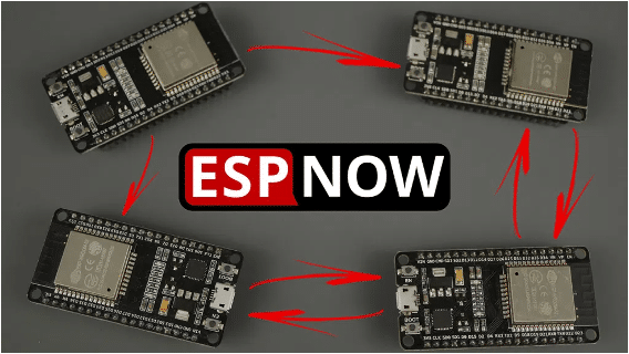
ESP-NOW is a protocol developed by Espressif, which permits a number of units to speak with each other with out utilizing Wi-Fi. The protocol is much like the low-power 2.4GHz wi-fi connectivity. The pairing between units is required previous to their communication. After the pairing is finished, the connection is secure and peer-to-peer, with no handshake being required. Because of this after pairing a tool with one another, the connection is persistent. In different phrases, if immediately considered one of your boards loses energy or resets, when it restarts, it would robotically connect with its peer to proceed the communication. In easy phrases, ESP-NOW is a quick communication protocol that can be utilized to alternate small messages (as much as 250 bytes) between ESP32 boards. ESP-NOW may be very versatile and you’ll have one-way or two-way communication in several setups.
ESP-NOW One-Method Communication
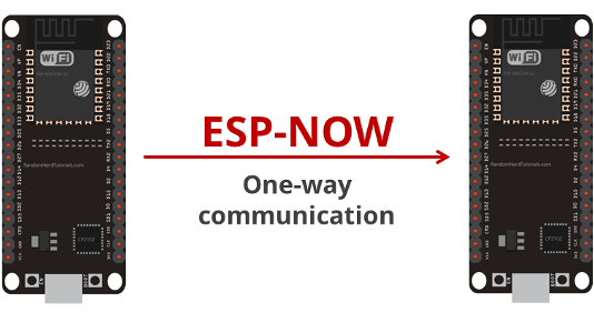
A method communication means One ESP32 board sending knowledge to a different ESP32 board.This configuration may be very straightforward to implement and it’s nice to ship knowledge from one board to the opposite like sensor readings or ON and OFF instructions to manage GPIOs. One ESP32 board sending the identical or completely different instructions to completely different ESP32 boards. This configuration is good to construct one thing like a distant management. To speak by way of ESP-NOW, it is advisable know the MAC Tackle of the ESP32 receiver. Every ESP32 has a novel MAC Tackle and that’s how we establish every board to ship knowledge to it utilizing ESP-NOW.
TP4056 Charger Module
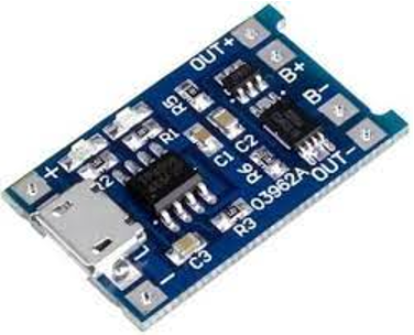
The TP4056 lithium battery charger module comes with circuit safety and prevents battery over-voltage and reverse polarity connection. The TP4056 module lights up a crimson LED when it’s charging the battery and lights up a blue LED when the battery is absolutely charged. join the battery constructive terminal to the B+ pad, and the battery damaging terminal to the B- pad. The OUT+ and OUT- are the battery outputs. These lithium batteries output as much as 4.2V when absolutely charged (though they’ve 3.7V marked within the label).
SPDT T- Kind Relay
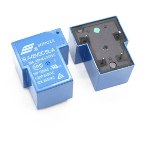
Single-pole, double-throw (SPDT) T-Kind relay proven in Fig, could be managed straight by way of a microcontroller utilizing relay driver circuit and change as much as 30A at 250V AC. The inputs of the relay are remoted from 230V mains to guard the fragile management circuitry. The relay output pins are linked to 3-pin 250V, 10A electrical socket.
Supply code
For Receiver:
#embrace
#embrace
int depend = 0;
// Construction instance to obtain knowledge
// Should match the sender construction
typedef struct struct_message {
char a[32];
int b;
float c;
bool d;
} struct_message;
// Create a struct_message known as myData
struct_message myData;
// callback operate that will likely be executed when knowledge is acquired
void OnDataRecv(const uint8_t * mac, const uint8_t *incomingData, int len) {
memcpy(&myData, incomingData, sizeof(myData));
Serial.print(“Bytes acquired: “);
Serial.println(len);
Serial.print(“Char: “);
Serial.println(myData.a);
Serial.print(“Int: “);
Serial.println(myData.b);
Serial.println();
if(myData.b == 1){
digitalWrite(2,HIGH);
depend =0;
}
if(myData.b == 0){
digitalWrite(2,LOW);
depend =0;
}
}
void setup() {
// Initialize Serial Monitor
Serial.start(115200);
pinMode(2,OUTPUT);
// Set gadget as a Wi-Fi Station
WiFi.mode(WIFI_STA);
// Init ESP-NOW
if (esp_now_init() != ESP_OK) {
Serial.println(“Error initializing ESP-NOW”);
return;
}
// As soon as ESPNow is efficiently Init, we are going to register for recv CB to
// get recv packer data
esp_now_register_recv_cb(OnDataRecv);
}
void loop() {
depend++;
delay(1000);
if(depend >= 10){
digitalWrite(2,LOW);
depend = 0;
}
}
For Transmitter:
#embrace
#embrace
#embrace
#embrace
#embrace
Adafruit_MPU6050 mpu;
int delay_sec = 5;
int depend;
// REPLACE WITH YOUR RECEIVER MAC Tackle
uint8_t broadcastAddress[] = {0x9C, 0x9C, 0x1F, 0xC8, 0x57, 0x84};
// Construction instance to ship knowledge
// Should match the receiver construction
typedef struct struct_message {
char a[32];
int b;
float c;
bool d;
} struct_message;
// Create a struct_message known as myData
struct_message myData;
esp_now_peer_info_t peerInfo;
// callback when knowledge is distributed
void OnDataSent(const uint8_t *mac_addr, esp_now_send_status_t standing) {
Serial.print(“rnLast Packet Send Status:t”);
Serial.println(standing == ESP_NOW_SEND_SUCCESS ? “Delivery Success” : “Delivery Fail”);
}
void setup() {
// Init Serial Monitor
Serial.start(115200);
// Set gadget as a Wi-Fi Station
WiFi.mode(WIFI_STA);
// Init ESP-NOW
if (esp_now_init() != ESP_OK) {
Serial.println(“Error initializing ESP-NOW”);
return;
}
// As soon as ESPNow is efficiently Init, we are going to register for Ship CB to
// get the standing of Trasnmitted packet
esp_now_register_send_cb(OnDataSent);
// Register peer
memcpy(peerInfo.peer_addr, broadcastAddress, 6);
peerInfo.channel = 0;
peerInfo.encrypt = false;
// Add peer
if (esp_now_add_peer(&peerInfo) != ESP_OK){
Serial.println(“Failed to add peer”);
return;
}
if (!mpu.start()) {
Serial.println(“Failed to find MPU6050 chip”);
whereas (1) {
delay(10);
}
}
Serial.println(“MPU6050 Found!”);
mpu.setHighPassFilter(MPU6050_HIGHPASS_0_63_HZ);
mpu.setMotionDetectionThreshold(1);
mpu.setMotionDetectionDuration(20);
mpu.setInterruptPinLatch(true); // Preserve it latched. Will flip off when reinitialized.
mpu.setInterruptPinPolarity(true);
mpu.setMotionInterrupt(true);
Serial.println(“”);
delay(100);
myData.b = 1;//preliminary ON
}
void loop() {
// Set values to ship
sensors_event_t a, g, temp;
mpu.getEvent(&a, &g, &temp);
depend++;
if(mpu.getMotionInterruptStatus()) {
strcpy(myData.a, “motion detect”);
myData.b = 1;
Serial.println(“motion detect”);
depend = 0;
}
if(!mpu.getMotionInterruptStatus()) {
if(a.acceleration.z > 7){
if(depend == delay_sec){
strcpy(myData.a, “no motion detect”);
myData.b = 0;
Serial.println(“no motion detect”);
depend =0;
}
}
}
esp_err_t outcome = esp_now_send(broadcastAddress, (uint8_t *) &myData, sizeof(myData));
if (outcome == ESP_OK) {
Serial.println(“Sent with success”);
}
else {
Serial.println(“Error sending the data”);
}
delay(1000);
}
Firmware description
The firmware for this method was developed in Arduino IDE utilizing embedded C. Adafruit MPU6050 and Adafruit sensor library recordsdata are added into Arduino IDE. As soon as the library file is put in, join the ESP32 improvement package to the pc utilizing USB cable and obtain the code for this method. The general stream of the firmware is proven in Fig.6. and Fig.7 .
