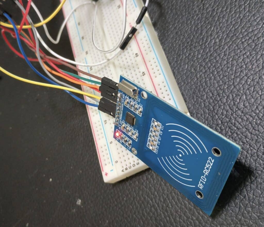
The IoT based mostly Entry and Exit Monitoring System is an RFID-based answer for monitoring people coming into and exiting a monitored space. Every particular person scans their distinctive RFID tag upon entry or exit, and the system data the motion.
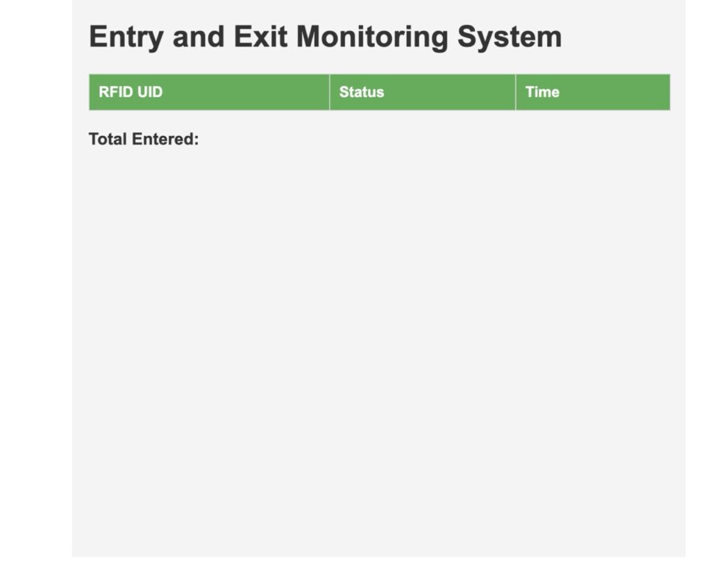
This data is displayed in real-time on an internet server, indicating whether or not the person is inside or has left the realm, with color-coded markers (inexperienced for entry and crimson for exit). Moreover, the net web page reveals the entire variety of individuals presently inside the realm.
Key Learnings
- RFID Know-how: Using RFID tags and readers for computerized identification and information seize.
- IoT Net Server: Establishing an internet server on ESP32 to show dwell information, making the system accessible remotely.
- Actual-time Monitoring: Capturing and displaying real-time entry and exit actions of people.
- Knowledge Dealing with: Storing and managing a number of RFID tags and their statuses.
Invoice of Materials
| Parts | Description | Amount |
| IndusBoard | 3cm sized dev board | 1 |
| Battery | 3.3V | 1 |
| Spherical Show | SSD1306/ GC9A01 | 1 |
| L89 GPS | GPS Module | 1 |
Use Case and Software
This method may be employed in numerous environments reminiscent of:
- Workplaces: Monitor staff coming into and exiting workplaces.
- Occasions: Monitor the attendance of individuals.
- Instructional Establishments: Automate attendance monitoring of scholars.
The RFID-based IoT system is straightforward and environment friendly, offering a real-time overview of who’s contained in the monitored space, making it appropriate for safety and monitoring functions.
Working Rationalization
- When an RFID tag is scanned, the system checks if it’s a new entry or a repeat scan.
- If it’s a new entry, the system logs the time, marks it as “entered” with a inexperienced dot, and will increase the counter of individuals inside.
- If the identical RFID tag is scanned once more, it’s marked as “exited” with a crimson dot, and the counter is decreased.
- This information is displayed in real-time on a webpage, displaying the present variety of individuals inside and their entry/exit statuses.
Disclaimer
This mission is designed for academic functions. For real-world deployment, please guarantee correct safety measures are taken, particularly with delicate information reminiscent of RFID tags linked to private data. Use a check setup with restricted funds or dummy information for verification earlier than full implementation.
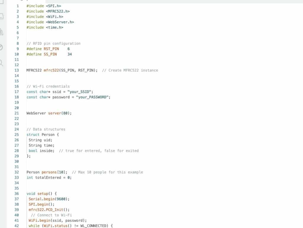
Code for IoT Entry and Exit Monitoring System
Rationalization
- Libraries and Definitions: Consists of vital libraries for SPI, RFID communication, and net server functionalities. Defines pin assignments and consumer information.
- Setup Perform: Initializes serial communication, SPI, MFRC522, and Wi-Fi. Units up net server routes for the basis URL and attendance web page.
- Loop Perform: Repeatedly checks for brand spanking new RFID playing cards. Reads the UID, compares it to saved UIDs, and updates attendance data. If an RFID card matches, it updates the punch-in or punch-out time and sends an replace message to the server.
- Net Server Handlers:
- handleRoot(): Serves a easy HTML web page with a hyperlink to view attendance.
- handleAttendance(): Serves an HTML web page with a desk displaying the attendance data. CSS kinds are used to format the desk for higher readability.
- getTime(): Offers the present date and time within the format “YYYY-MM-DD HH:MM
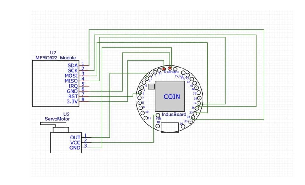
IoT based mostly Entry and Exit Monitoring System – Circuit Connection
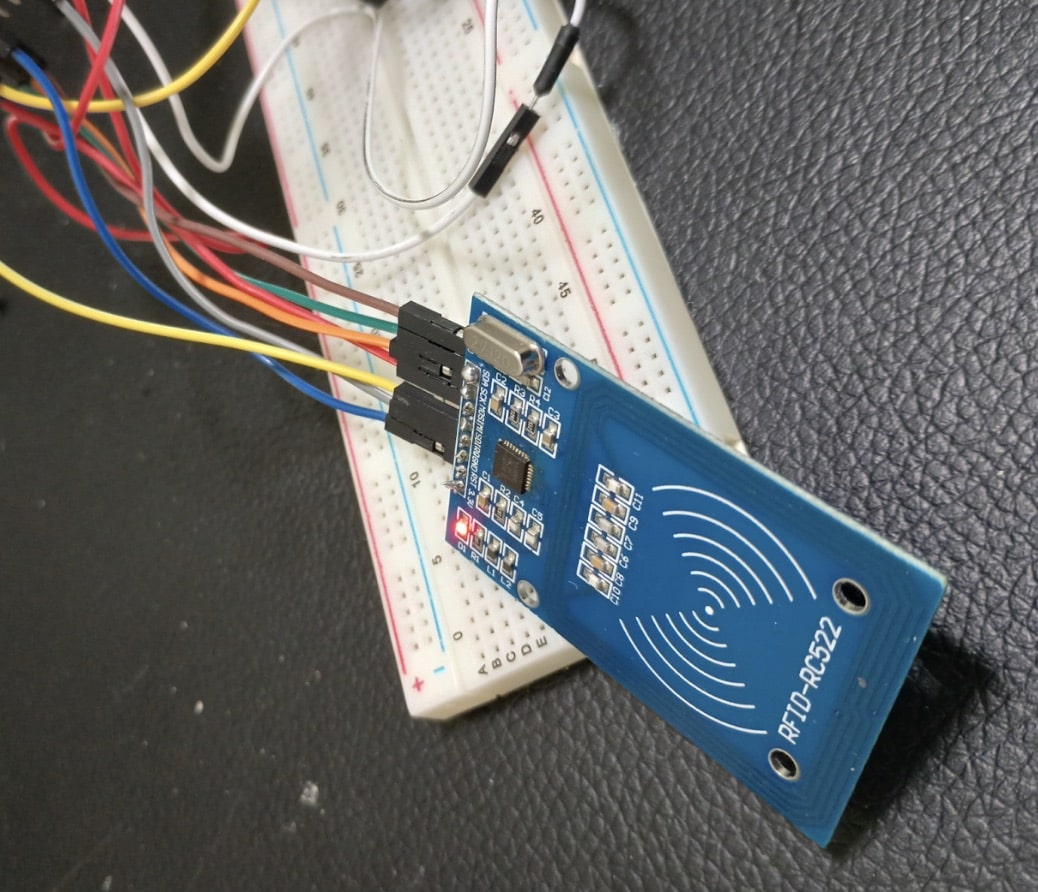
Now join the RFID to SPI pins of the INDUSBoard Coin as per circuit diagram.
Testing
- Add the Code: Use the Arduino IDE to add the code to your IndusBoard Coin
- Hook up with Wi-Fi: Make sure the ESP32 is related to the Wi-Fi community.
- Entry Net Server: Open an internet browser and navigate to the IP handle of the ESP32. You need to see a web page with a hyperlink to view attendance data.
- Scan RFID Playing cards: Take a look at scanning the RFID playing cards and confirm that the attendance data are up to date appropriately on the internet web page.
- Actual-Time Updates: Refresh the attendance web page to see real-time updates as you scan completely different RFID playing cards.
This mission offers a sensible introduction to IoT, net growth, and RFID know-how, permitting you to construct a real-time attendance system with a contemporary net interface.
