The most typical trigger of fireplace in a kitchen is fuel leakage. This challenge will enable you make an LPG leakage cum smoke detector kitchen safety alarm utilizing a fuel sensor. The sensor will detect the depth of LPG fuel in addition to smoke, if any. If the depth of LPG fuel or smoke exceeds a sure restrict, an audible alarm will notify you to care for the leakage as quickly as attainable.

LPG/smoke detectors are superb gadgets as they’re small and low-cost, but very helpful. MQ2 is the commonest steel oxide semiconductor (MOS) sort of fuel sensor. It is rather delicate to smoke and flammable gases like LPG, butane, propane, methane, alcohol, hydrogen, and carbon monoxide. When a fuel is available in contact with the sensor, the circuit makes use of a easy voltage divider community to detect it.
You may also examine the fuel leakage detector that we construct beforehand.

The MQ2 sensor has two electrodes fabricated from aluminum oxide (Al2O3) and a heating ingredient fabricated from tin dioxide (SnO2) that acts as the principle sensing layer.
| Kitchen Safety Alarm Components Listing | ||
| Semiconductors: | ||
| IC1 | -LM7805, 5V voltage regulator | |
| IC2 | -LM358 op-amp | |
| IC3 | -NE555 timer | |
| T1, T2 | -2N2219 NPN transitor | |
| BR1 | -1A bridge rectifier | |
| LED1 | -5mm LED | |
| D1 | -1N4007 rectifier diode | |
| Resistors (all 1/4-watt, ±5% carbon): | ||
| R1, R2, R4, R5 | -1-kilo-ohm | |
| R3, R7 | -680-ohm | |
| R6 | -1-mega-ohm | |
| Capacitors: | ||
| C1 | -1000μF, 35V electrolytic | |
| C2 | –1000μF, 16V electrolytic | |
| C3 | -10nF ceramic disk | |
| Miscellaneous: | ||
| Exhaust fan | -230V AC operated | |
| RL1 | -5V, SPDT relay | |
| CON1-CON3 | -2-pin connector | |
| Sensor1 | -MQ2 fuel sensor | |
| X1 | -230V AC main to 9V, 500mA secondary transformer | |
Kitchen Safety Alarm – Circuit Connections
The circuit diagram of the alarm utilizing MQ2 sensor is proven in Fig. 1. The circuit is constructed round step-down transformer X1, bridge rectifier BR1, 5V voltage regulator LM7805 (IC1), MQ2 sensor (Sensor1), op-amp LM358 (IC2), timer NE555 (IC3), 5V SPDT relay RL1, a piezo buzzer (BZ1), and some different parts. Capacitor C1 related throughout the provision terminals minimizes voltage ripples and any noise alerts.
The circuit wants 5V DC to function, which is derived from the 9V, 500mA secondary facet of transformer X1. The 230V AC mains energy provide is related to the first of X1 by way of connector CON1 within the circuit. The 9V AC secondary of X1 is related to bridge rectifier BR1 for rectification. The rectified voltage filtered by capacitor C1 is given to IC LM7805 to get regulated 5V for the circuit. LED1 signifies the supply of 5V.
The output of the MQ2 sensor is given to the non-inverting pin 3 of IC LM358, which acts as a comparator on this circuit. The inverting pin 2 of LM358 is related to pot VR1 in order that the sensitivity of the circuit might be adjusted. The output of LM358 is given to the bottom of the buzzer driver transistor T1 by way of resistor R7. The buzzer is supposed to lift an alarm.
Bonus: You’ll be able to examine the step-by-step full video tutorial of this challenge from the beneath link-
Safety Alarm Video Tutorial
Kitchen Safety Alarm – Working
The working of the circuit is easy. After connecting 230V AC throughout CON1, when energy is switched on, LED1 glows to point that the circuit is able to use. In case of smoke or fuel leakage past the set restrict, the MQ2 sensor’s output goes larger at pin 3 of IC LM358 than the reference voltage at pin 2. Thus, the output of op-amp IC LM358 at its pin 1 goes excessive. Consequently, transistor T1 conducts and the buzzer sounds to point smoke or fuel leakage.
Additionally, on the identical time, IC NE555 triggers and transistor T2 conducts to energise relay RL1. If an exhaust fan is related between the widespread and usually closed contacts of the relay, it would swap on and maintain working for round 18 minutes due to timer IC NE555 which has been wired in monostable multivibrator mode.
Right here, the NE555 timer IC has been wired in monostable multivibrator mode. Primarily based on the above-mentioned timing parts resistor R6 and capacitor C2, the on-time output of IC3 will likely be round 18 minutes.
This output pulse of NE5555 stays excessive based mostly on its pulse width, which units the predefined time interval. This time interval might be set by deciding on the values of resistor R6 and capacitor C2 utilizing the connection:
Output Pulse Width (secs)=1.1 ×R6×C2
On this circuit, the worth of R6= 1M and the worth of C2=1000µF. So, if we calculate the time in seconds, it is going to be round 1100 seconds, which is roughly 18 minutes.
As we’re utilizing the MQ2 sensor to match the output voltage of LM358 with the reference voltage, to calibrate the sensor, set the reference voltage to round 0.5V utilizing pot VR1. Then create some smoke or LPG fuel leakage close to the sensor. After a while, the output at pin 3 of op-amp LM358 would go larger than the reference voltage at pin 2. It will make the output at pin 1 of LM358 set off the buzzer. If the buzzer sounds, it means the calibration is profitable. If the buzzer doesn’t sound, modify pot VR1.
PCB Design
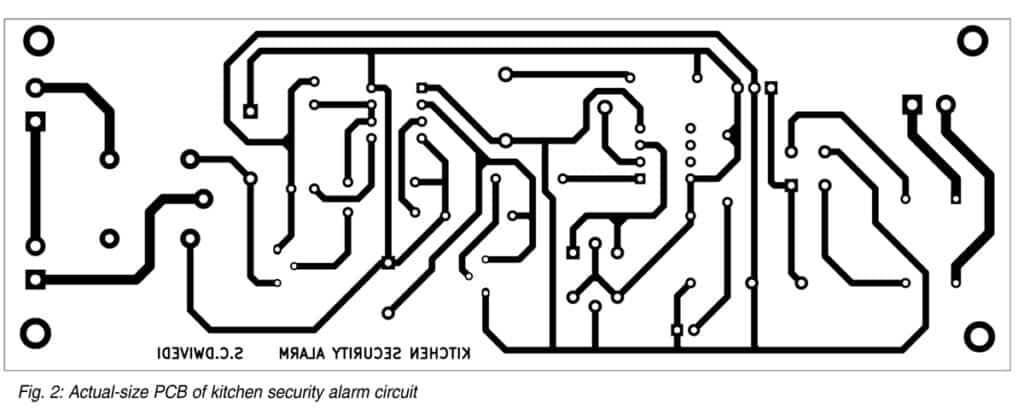
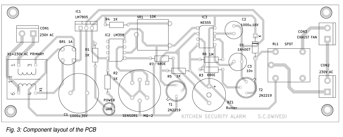
An actual-size, single-side PCB format for the safety alarm is proven in Fig. 2 and its part format in Fig. 3. After assembling the circuit on PCB, enclose it in an acceptable field. Repair LED1 and CON2 in entrance of the field and join the exhaust fan on the rear facet of the field.
After assembling the circuit, set up the unit not too removed from the fuel range, in order that when fuel leaks or there’s extreme smoke within the space, it may be simply accessed by the sensor.
Obtain PCB and Part Format PDFs: click on right here
S.C. Dwivedi is an electronics fanatic and circuit designer at EFY

