
This sound alternator is designed to simulate the results of a police siren, combining sound and light-weight to create a dynamic audio-visual expertise. It makes use of an ESP32, a small speaker, and two pink LEDs to alternate between sound alerts and blinking lights. Management is achieved by code written within the Arduino IDE or MicroPython, utilising the GPIO pins of the ESP32.
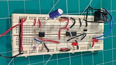
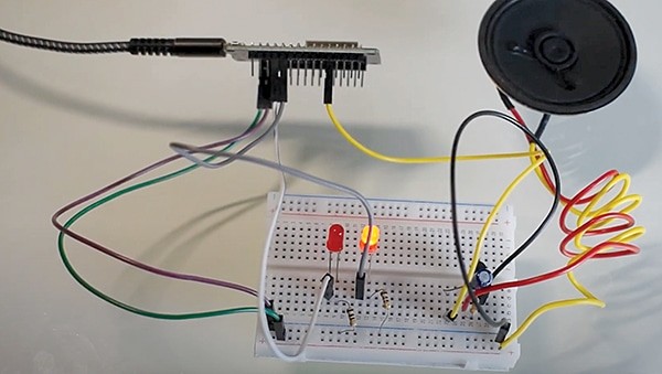
The ESP32 regulates the sound frequency, enabling the speaker to imitate the distinct tones of a police siren. Concurrently, it controls the voltage throughout the LEDs, inflicting them to alternate in illumination. Fig. 1 showcases the prototype on a breadboard, with the required elements listed within the Invoice of Supplies desk.

| Invoice of supplies | |
| Elements | Amount |
| ESP32 (MOD1) | 1 |
| 0.5W speaker (SP1) | 1 |
| BC547 transistor (T1) | 1 |
| 10µF, 16V capacitor (C1) | 1 |
| 100kΩ resistor (R3) | 1 |
| 100Ω resistor (R1, R2) | 2 |
| 5mm pink LEDs (LED1, LED 2) | 2 |
Circuit and dealing
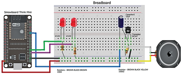
Fig. 2 exhibits the circuit diagram of the sound alternator, which is constructed utilizing the ESP32 board, BC547 transistor, two pink LEDs, a speaker, and different elements.
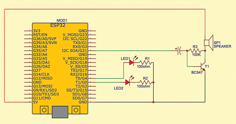
The circuit features a transistor linked to a breadboard. A 100k resistor is positioned throughout the bottom and collector junction of the transistor. The capacitor’s damaging terminal is linked to the bottom of the transistor, and its optimistic terminal is linked to pin G21 of the ESP32.
One terminal of the speaker is linked to the 5V pin of the ESP32, whereas its different terminal is linked to the collector of the transistor. The emitter of the transistor is grounded by connecting it to the ESP32’s floor pin. To restrict the present, the LEDs are additionally grounded by way of 100-ohm resistors (R1 and R2).
The anode of LED1 is linked to pin G4 of the ESP32, whereas the anode of LED2 is linked to pin G0. Each LEDs and the speaker are managed by the ESP32.
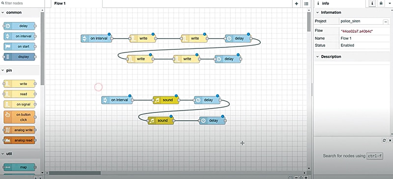
The code could be developed in IDEs equivalent to MicroPython, Arduino IDE, or comparable. SmowCode has been used right here to create the code for the machine. As proven in Fig. 3, code blocks are joined. The board needs to be chosen as ESP32-S2, and the code needs to be uploaded to the machine.
Development and testing
To assemble and check the machine, obtain the firmware in .bin format from the web site or create code by modifying the nodes.
As soon as the code blocks are set (consult with Fig. 3), add the code to the ESP32 board after choosing the right COM port and board.
Assemble the machine on the breadboard as per the wiring diagram in Fig. 4.
Energy the machine. As soon as powered, the LEDs will alternate in illumination, and the speaker will produce a sound mimicking a police siren.
Supply Code will likely be shared quickly.
Shaikh Faiza is a passionate electronics engineer.

