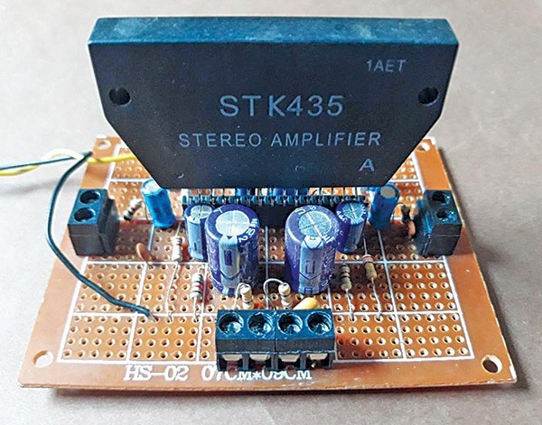

This stereo AF amplifier makes use of the STK435 IC, a extremely common alternative resulting from its simplicity. The STK435, with its 15-pin configuration, requires just a few exterior parts, comparable to electrolytic and ceramic capacitors and resistors.
With a 12V DC energy provide, the amplifier delivers roughly 7 watts to an 8-ohm speaker, providing wonderful audio high quality. The creator’s prototype is proven in Fig. 1.
| Components Listing |
| Semiconductor: IC1 (IC1A, IC1B): 15-pin STK435 stereo amplifier IC Resistors (All 1/4-watt, ±5% Carbon) R1, R15: 1 kΩ R2, R12, R4, R14: 220 kΩ R3, R13: 390 kΩ R5: 100 Ω R6, R11: 120 Ω R7, R9: 4.7 Ω R8, R10: 12 kΩ Capacitors C1, C13: 470 pF ceramic disk C2, C12: 0.47 µF, 25V electrolytic C3, C11: 10 µF, 25V electrolytic C4, C9: 220 µF, 25V electrolytic C5, C10: 47 µF, 25V electrolytic C6, C7: 1000 µF, 25V electrolytic C8, C14: 0.1 µF ceramic disk C15: 100 µF, 25V electrolytic Miscellaneous CON1-CON3: 2-pin connectors LS1, LS2: 8-ohm, 7-watt audio system with 2-pin connectors Board: 7 cm x 9 cm Veroboard Energy Supply: 12V battery Warmth Sink: For IC STK435 |

Additionally Test: Stereo AF Amplifier Utilizing TDA1517
Stereo AF Amplifier – Circuit and Working
The circuit diagram of the STK435-based stereo amplifier is proven in Fig. 2. The design contains the STK IC, resistors, and capacitors, with two audio inputs and corresponding amplified outputs for the precise and left channels.
Begin by finishing the connections for the primary amplifier part of IC1, known as IC1A. Pin 1 connects to 2 resistors (R2 and R3) in sequence, adopted by a 100-ohm resistor (R5) resulting in the +12V provide. A 10µF, 25V electrolytic capacitor (C3) is linked between the junction of R2 and R3 and the bottom. A 0.47µF, 25V electrolytic capacitor (C2) connects to pin 1 of IC1, with its unfavorable terminal linked to a 1-kilo-ohm resistor (R1). Moreover, a 470pF ceramic capacitor (C1) connects the unfavorable terminal of C2 to floor.
Pin 2 connects to the bottom via an electrolytic capacitor of 220µF, 25V (C4) in sequence with a 120-ohm resistor (R6). Pins 3, 4, and eight are additionally grounded. The output from pin 5 drives an 8-ohm, 7-watt speaker (LS1) by way of a 1000µF, 25V electrolytic capacitor (C6). The unfavorable polarity of C6 connects to floor via a sequence association of a 0.1µF capacitor (C14) and a 4.7-ohm resistor (R7).
Pin 6 connects to pin 5 via a 47µF, 25V electrolytic capacitor (C5). Pin 7 is linked to the +12V provide, whereas pin 9 connects to +12V via a 100-ohm resistor (R5). A 12-kilo-ohm resistor (R8) bridges pins 2 and 5. A 100µF, 25V electrolytic capacitor (C15) connects pin 9 to floor.
The second amplifier part, IC1B, makes use of pins 10 via 15 and is linked as proven in Fig. 2.

This circuit operates merely: join audio inputs (from units comparable to laptops, desktops, or MP3 gamers) to CON1 and CON3, then join a 12V energy provide. The amplified output will likely be heard via the audio system.
Additionally Test: Low-Price Stereo Audio Amplifier Circuit Beneath 50 Rupees
Building and Testing
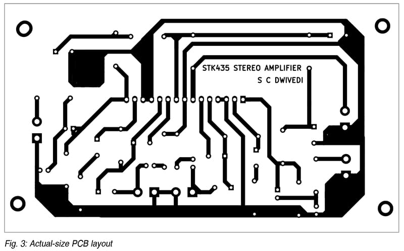
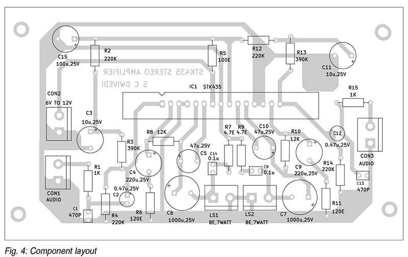
An actual-size single-sided PCB structure for the STK435 amplifier is proven in Fig. 3, with the element structure in Fig. 4. After assembling the circuit on the PCB, enclose it in an acceptable cupboard, guaranteeing correct warmth dissipation for the IC with an applicable heatsink.
Alternatively, a 7cm x 9cm Veroboard can be utilized. Place a 15-pin feminine connector in the course of the board, two 2-pin connectors on the far proper and left sides, and a 4-pin connector on the backside. Solder all parts as indicated within the circuit diagram, utilizing a low-watt soldering iron. The IC ought to be inserted after soldering. Join two 8-ohm, 7-watt audio system to the 2-pin connectors, and provide energy utilizing a 12V battery. A clicking sound from the audio system could point out correct connection.
After assembling on both the PCB or a Veroboard, the system is prepared for testing. Gently contact a steel screwdriver to the 2-pin connectors to listen to a buzzing sound from the audio system, confirming performance. As soon as examined, join an MP3 participant, laptop computer, or desktop to the amplifier’s enter and benefit from the audio output.
Raj Ok. Gorkhali is an electronics hobbyist and an everyday contributor to EFY

