
With this dry working safety system, you’ll be able to forestall your water cooler’s motor from dry working and activate it for about one-third of the time solely. It will cut back the wear and tear and tear of the motor and save electrical energy too. Coolers are utilized in many houses, workplaces, colleges, and industries, particularly in summer season.
So this system will turn out to be useful to cease the cooler pump mechanically when the cooler’s tank has no water.
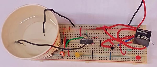
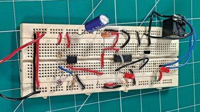
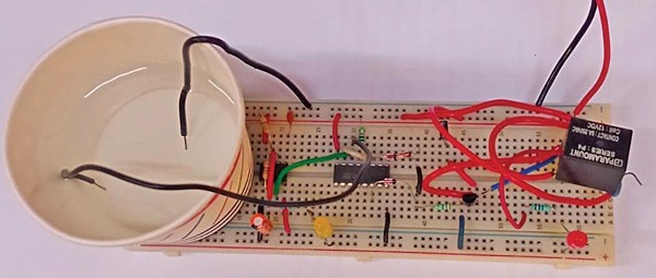
DIY Dry Operating Safety System for Pump is proven in Fig. 1 and its circuit diagram is proven in Fig. 2.
| Parts Required for Constructing Dry Operating Safety System | |
| Semiconductors: | |
| IC1 | -LM7805, 5V voltage regulator |
| IC2 | -NE555 timer |
| IC3 | -4017 decade counter |
| BR1 | -1A bridge rectifier |
| LED1, LED2 | -5mm LED |
| D1 | –1N4007 rectifier diode |
| D2-D5 | -1N4148 sign diode |
| T1 | -2N2219 NPN transistor |
| Resistors (all 1/4-watt, ±5% carbon): | |
| R1, R6 | -1-kilo-ohm |
| R2 | -470-kilo-ohm |
| R3 | -47-kilo-ohm |
| R4 | -10-kilo-ohm |
| R5 | -680-ohm |
| Capacitors: | |
| C1 | -1000μF, 35V electrolytic |
| C2 | -100μF, 16V electrolytic |
| C3 | -10nF ceramic disk |
| Miscellaneous: | |
| CON1-CON4 | -2-pin connector |
| S1 | -Water sensor probes manufactured from metal (2) |
| RL1 | -5V, 1C/O relay |
| X1 | -230V AC major to 9V, 500mA secondary transformer |
| -Cooler pump | |
DIY Dry Operating Safety System – Circuit Diagram
The circuit contains step-down transformer X1, bridge rectifier BR1, 5V voltage regulator LM7805 (IC1), decade counter 4017 (IC2), rectifier diode 1N4007 (D1), sign diode 1N4148 (D2-D5), NPN transistor 2N2219 (T1), 5V single changeover relay, and some different parts.

The 5V DC provide required for the circuit is derived from 230V AC to 9V, 500mA step-down transformer X1. The 230V AC mains is linked to the first winding of X1 through CON1 within the circuit. The secondary winding of X1 produces 9V AC, which is linked to bridge rectifier BR1 for rectification and to capacitor C1 for filtration.
The rectified and filtered voltage is given to regulator IC LM7805 (IC1) to get regulated 5V for the circuit, whose presence is confirmed by the glowing LED1.
The 555 timer IC2 is wired in astable multivibrator mode. Primarily based on the values of timing parts R2, R3, and C2, the frequency of the output pulse is round 0.26Hz and its time interval is round 40 seconds. This frequency will be modified by altering the timing parts’ values.
Instead of R3, you should use a pot to range the output frequency. The flashing of LED2 signifies that the astable multivibrator is working effectively.
The clock pulse of the 555 Timer at its pin 3 is given to pin 14 of decade counter 4017 (IC3).
Pin 16 of decade counter IC3 is linked to produce and pin 8 (floor). Pin 13 (inhibit) and pin 15 (reset) collectively are linked to 5V through 10k resistor R4. These two pins are additionally linked to water sensor probes which are used to allow IC3.
One probe of the water sensor is linked to the junction of pins 13 and 15 and the opposite probe is linked to the circuit’s floor by way of CON1.
The six outputs Q1, Q2, Q3, This fall, Q5, and Q6 of IC3 will not be used. Its remaining three outputs Q7, Q8, and Q9 are linked to the anodes of respective 1N4148 diodes D2 by way of D4. The cathodes of D2 by way of D4 diodes are linked to one another and to the bottom of transistor T1 by way of resistor R5.
Solely Q7, Q8, and Q9 output pins of IC 4017 are used to drive the relay to extend the off time of the pump. The pump stays off when the seven outputs Q1 by way of Q6 are excessive.
Dry Operating Safety System – Working
Full the connections and energy on 230V AC. Relay RL1 is pushed by transistor T1 when outputs Q7, Q8, and Q9 of IC2 go excessive to activate the cooler’s pump. The pump will run solely when water is offered within the cooler’s water storage tank, which is sensed by the sensor probe to allow IC2. The motor will run for round 1/third time and stay off for two/third time.
When there may be enough water within the cooler’s water tank, the junction of pins 13 and 15 stays low due to water touching the sensor probe. On this case, IC3 switches the cooler pump on/off sequentially. When water is inadequate, the junction of pins 13 and 15 goes excessive. On this case, IC2 switches off the cooler pump in order that it doesn’t run dry.

An actual-size, single-side PCB structure for the cooler pump’s security circuit is proven in Fig. 3 and its part structure in Fig. 4. After assembling the circuit on PCB, enclose it in an appropriate field. Repair LED1 and CON4 on entrance aspect of the field and the mains connector’s CON2 and pump connector CON3 on the rear aspect.

Take water sensor probes manufactured from metal rods, as they need to be corrosion-free, and join them to CON2. The opposite terminals of sensors ought to be fastened to the cooler’s physique in such a approach that distance between the probes is 30mm to 40mm they usually get shorted when there may be ample water.
Bonus: You may watch the step-by-step information to creating this Dry Operating Safety System for Pumps-
S.C. Dwivedi is an electronics fanatic and circuit designer at EFY

