This mission is a standalone automated fan tempo controller that controls the tempo of {{an electrical}} fan in response to the requirement. Use of embedded know-how makes this closed-loop feedback-control system atmosphere good and reliable. The microcontroller (MCU) ATMega8/168/328 permits dynamic and sooner administration and the LCD makes the system user-friendly. Sensed temperature and fan tempo ranges are concurrently displayed on the LCD panel.
The mission may very successfully be very compact and makes use of numerous elements solely. It might be utilized for numerous options along with air-conditioners, water-heaters, snow-melters, ovens, heat-exchangers, mixers, furnaces, incubators, thermal baths and veterinary working tables. The mission will help save vitality/electrical vitality.
Circuit and dealing

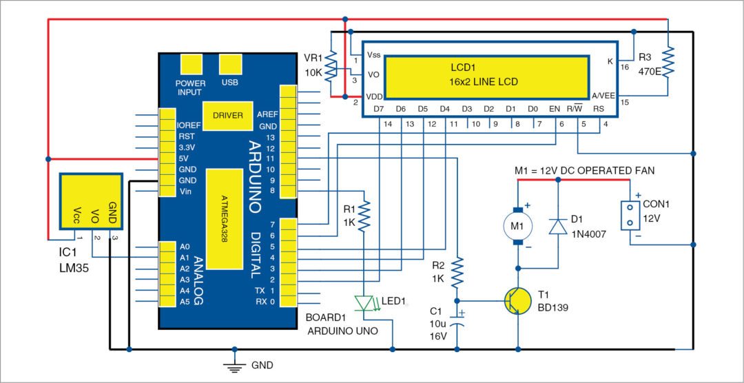
Circuit diagram of the temperature fan tempo administration and monitoring is confirmed in Fig. 1. It is constructed spherical Arduino Uno board (Board1), 16×2 LCD (LCD1), temperature sensor LM35 (IC1) and a few fully completely completely different elements.
Arduino is on the coronary coronary coronary coronary heart of the circuit on account of it controls all capabilities. LM35 is a precision built-in circuit whose output voltage is linearly proportional to Celsius (Centigrade) temperature. It is rated to hold out over a -55°C to 150°C temperature range. It has +10.0mV/Celsius linear-scale disadvantage.

Temperature sensor LM35 senses the temperature and converts it into {{{{an electrical}}}} (analogue) signal, which is utilized to the MCU through an analogue-to-digital converter (ADC). The analogue signal is reworked into digital format by the ADC. Sensed values of the temperature and tempo of the fan are displayed on the LCD. Temperature and monitoring using Arduino The MCU on Arduino drive the motor driver to deal with fan tempo.
Fan tempo administration methodology
A low-frequency pulse-width modulation (PWM) signal, typically all via the range of about 30Hz, whose accountability cycle is assorted to deal with the fan’s tempo is used. An reasonably priced, single, small change transistor shall be utilized right correct proper right here. It is atmosphere good as a result of change transistor is used as a change.
One draw again of this method, nonetheless, is that it may presumably make the fan noisy on account of pulsed nature of the signal. The PWM waveform’s sharp edges set off the fan’s mechanical setting up to maneuver (like a badly-designed loudspeaker), which could merely be audible.
Establishing and testing

A single-side PCB for the temperature-based fan tempo administration and monitoring circuit is confirmed in Fig. Three and its half format in Fig. 4. Assemble the circuit on the PCB.

CON2 and CON3 are used to connect Board1 (Arduino UNO board) through exterior connectors. A 12V battery is used to drive the 12V DC-operated fan.
Buy PCB and Half Format PDFs: click on right here
Software program program program program
Software program program program program for the automated temperature controller and monitor circuit is written in Arduino programming language. Arduino Uno is programmed using  Arduino IDE software program program program program.
ATmega328P on Arduino Uno comes with a pre-programmed bootloader that allows customers so as in order so as to add a model new code to it with out using an exterior {{{{hardware}}}} programmer.
Be part of Arduino board to the PC and select the right COM port in Arduino IDE. Compile this methodology (sketch). Then select the right board from Devices Board menu in Arduino IDE and add the sketch (abfc.ino) to Arduino through customary USB port.

