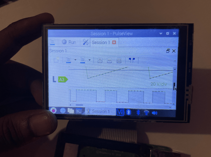
 Probably the most important instrument for engineers is a logic analyzer, which they function utilizing a laptop computer or PC to point out the outcomes. A stand-alone analyzer with a show can value you round 10 thousand rupees or extra. So, right this moment we’ll design a low-cost logic analyzer that has its personal stand-alone show that’s moveable and could be carried within the pocket. Therefore, do your design and use this instrument with out worrying in regards to the laptop computer or PC for viewing the info. The system could be designed by configuring the next parts.
Invoice Of Supplies
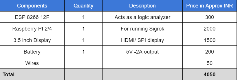
Be aware: The show half is optionally available and attachable like an adjunct. Therefore, if you wish to take away the show, then the ESP is itself a logic analyzer, and additional, to examine real-time information on a PC, set up the Sigrok. It is going to value you solely INR 350 if you happen to detach the show.
Coding
For the logic analyzer, we program the ESP 8266. Therefore, it acts as a USB logic analyzer. We will join the circuit or system’s output pins to the ESP GPIO, which acts as a channel for the logic analyzer. For that, we have to set up the analyzer library. Open the Arduino IDE after which go to Sketch and Clock. Add the library utilizing zip. Now add the analyzer library by choosing the zip file of the library. Obtain the library utilizing the next hyperlink.
Now we will code the analyzer. Open the Arduino IDE after which choose the ESP logic analyzer instance code. Now within the code, we will arrange frequency, baud fee, and different configurations.
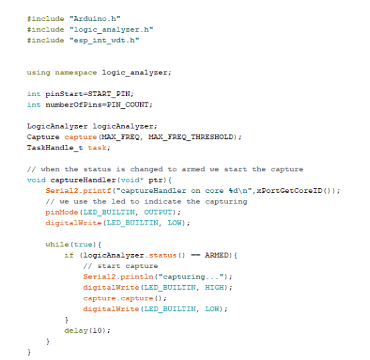
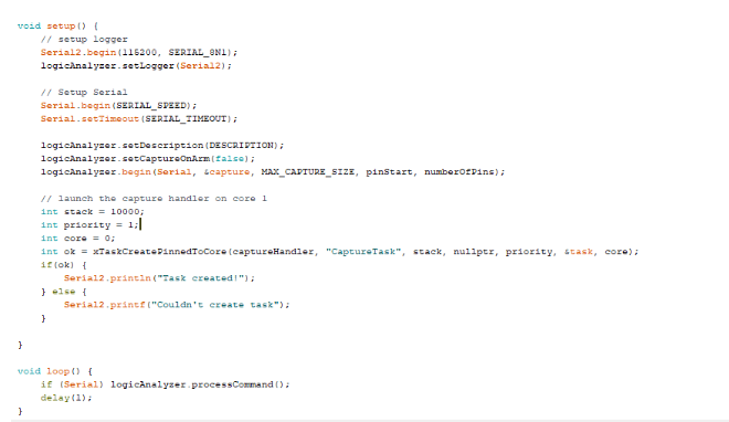
Now we have to choose the proper port quantity and the proper ESP8266 board and add the code.
Connection
Now join the FTDI and channel GPI as follows. The Logic analyzer channel GPIO are 13 to 16
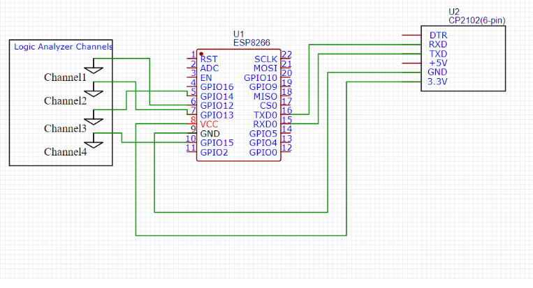
Now our analyzer is prepared, however our system can seize the logic information utilizing GPIO pins, which act as a channel for the analyzer, however we will’t view it with none software program, so when you’ve got a PC or laptop computer, then set up the Sigrok utilizing the next hyperlink.
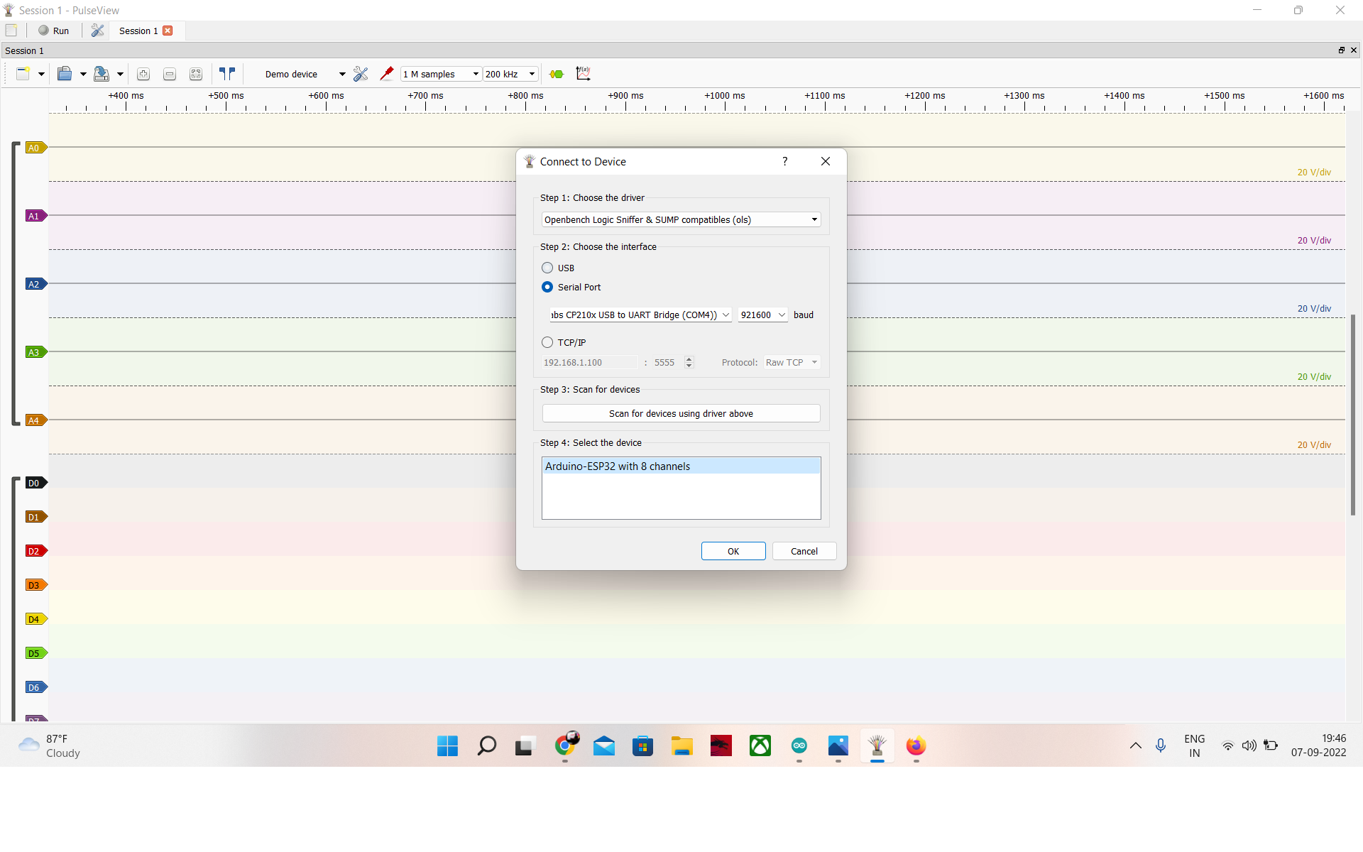
Now open the Sigrok Pulseview after which go to attach and choose the Open Bench logic snipper. Now, choose the serial port and baud fee after which scan for the system. After scanning, you’ll obtain the identify of the analyzer system. The identify used for this system is the ESP board. It exhibits ARDUINO ESP with 8 channels. Choose it, and now your 4-channel logic analyzer is prepared.

Develop a Transportable Show
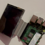
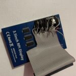
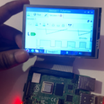
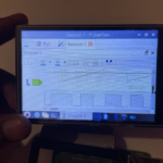
Now, to make the system a standalone analyzer that wants no laptop computer or PC, develop a small information displaying system that’s moveable and sufficiently small to be carried anyplace. Set up the newest OS on the Raspberry Pi, then set up the SIGROK Pulseview on Raspbian OS, and arrange the show driver. In case you are utilizing an HDMI show, then you do not want any drivers, however in case you are utilizing an SPI show, then set up the show driver. Each show consists of its personal driver and varies with show kind. Therefore, observe the respective directions for the driving force offered. Now join the feminine GPIO of the show to the Raspberry Pi’s male GPIO, aligning it in line. In the event you should not have the feminine GPIO on the Raspberry Pi show however solely have male pins, then lower the feminine GPIO extender of the Raspberry and join the wires to the show pins. Then join the tip of the feminine GPIO to the Raspberry Pi as within the pic beneath . Then repair all of the parts.
Testing
Now the system is prepared, energy the raspberry pi with 5V and insert the ESP USB into the Raspberry Pi. Now, open the Pulseview and choose the ESP system, and join it as a analyzer. The ESP pins can be utilized as a channel for the analyzer; join it to the pins for doing sign evaluation. The sign evaluation could be seen on the show related.

