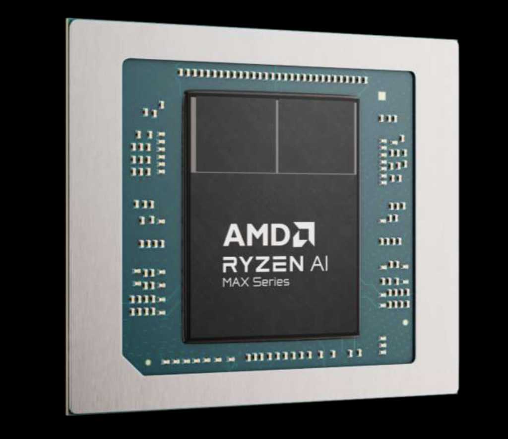
AMD has launched what one govt known as “the most advanced mobile X86 processor ever created” at CES 2025: The Ryzen AI Max and AI Max+, with completely huge capabilities to run graphics and AI workloads.
AMD is positioning this “Strix Halo” chip as a form of hybrid for graphics and AI workstations, evaluating it to Nvidia’s present GeForce 4090 GPU by way of operating AI LLMs at as much as 70 billion parameters. However the Ryzen AI Max presents extra than simply that.
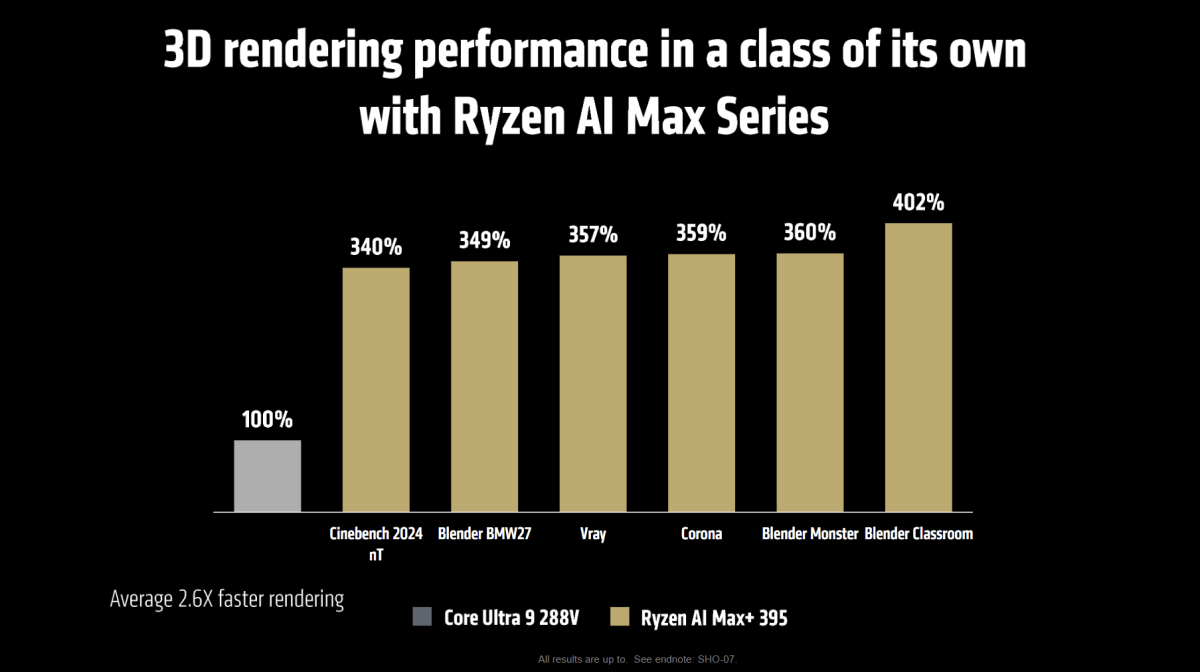
It’s an APU with graphics capabilities that push into discrete GPU territory — within the 3DMark Metal Nomad benchmark, for instance, the chip presents 258 p.c the graphics efficiency of Intel’s Core Extremely 9 288V (Arrow Lake) CPU. It additionally presents glorious AI efficiency, each with or with out the NPU.
The subtext behind this announcement hearkens again to our report early final 12 months that the NPU doesn’t matter for AI capabilities as a lot as AMD, Intel, or Qualcomm initially hyped.
The NPU is essentially the most environment friendly AI core on fashionable CPUs. However for uncooked horsepower, the GPU, particularly a discrete GPU, far outperforms both the NPU or the GPU by its lonesome. What the AI Max seems to do is mix among the NPU and GPU’s greatest options, alongside an already highly effective AMD Zen 5 CPU.
AMD will provide the Ryzen AI Max in each client and “Pro” variations, which the corporate will promote to companies. At CES, AMD is touting three design wins, together with the HP ZBook Extremely G1a and Z2 Mini G1a mini workstations, plus the Asus ROG Movement Z13 pill.
AMD
“This is something very, very special,” mentioned Rahul Tikoo, the senior vice chairman and common supervisor of AMD’s shopper computing enterprise mentioned in a recorded briefing for reporters.
“It’s just so unique and powerful. It enables incredible performance and reshaping what customers can experience from the power of workstation and thin-and-light laptops to incredibly small and powerful micro desktops. This is simply the most advanced mobile x86 processor ever created.”
AMD’s Ryzen AI Max and its options
Curiously, AMD is providing 4 of the AI Max chips as industrial merchandise — the Ryzen AI Max+ Professional 395, the Ryzen AI Max Professional 390, the Ryzen AI Max Professional 385, and the Ryzen AI Max Professional 380. Nevertheless, the primary three are being supplied in consumer-friendly non-Professional variations.
- Ryzen AI Max+ 395: 16 cores/32 threads, 5.1GHz turbo, 80MB cache; 40 graphics cores; 50 peak TOPS, 45-120W cTDP
- Ryzen AI Max 390: 12 cores/24 threads, 5.0GHz turbo, 76MB cache; 32 graphics cores; 50 peak TOPS; 45-120W cTDP
- Ryzen AI Max 385: 8 cores/16 threads, 5.0GHz, 40MB cache; 32 graphics cores; 50 peak TOPS; 45-120W cTDP
The fourth chip, the Ryzen AI Max Professional, is a 6 core/12-thread half with 22MB of cache and operating at 4.9GHz. All of those shall be accessible in both the primary or second quarter of 2025, AMD mentioned.
AMD
What’s attention-grabbing in regards to the AI Max elements is that they’re actually not differentiated by clock velocity. As an alternative, CPU cores depend, the variety of graphics CUs and particularly the cache measurement separate the three chips. (It’s not fairly clear what AMD means by ay the AI Max+ versus the extra generic AI Max.)
What this chip doesn’t seem to have is the stacked V-Cache that differentiates AMD’s Ryzen X3D chips — simply loads of what seems to be abnormal degree 3 cache.
In graphics, AMD has solely launched two RDNA 3.5 GPUs, the Radeon 880M and 890M, that are a part of the “Strix Point” CPU structure that makes up the Radeon AI 300. These chips boast 12 CUs and 16 CUs, respectively, far lower than what the brand new Ryzen AI Max chips embody.
Alternatively. the Radeon 7000 sequence contains each the Radeon 7600XT in addition to the Radeon 7700XT, which boast 32 CUs and 54 CUs. Each of these GPUs use the older RDNA 3.0 structure. (Learn our Radeon 7600 evaluation in addition to our Radeon 7700XT evaluation for extra particulars.)
AMD
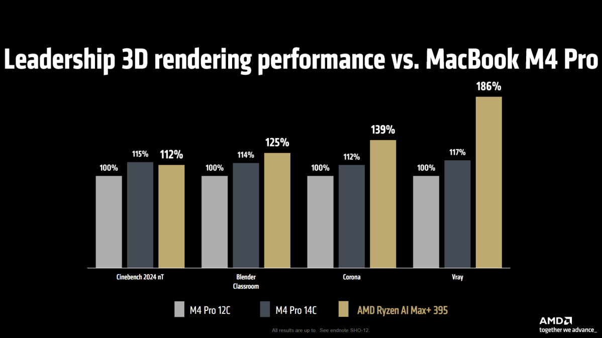
AMD executives mentioned that the Ryzen AI Max sequence is designed with an 256GB/s coherent reminiscence interface of unknown width that may deal with as much as 96GB of graphics reminiscence. However, that’s near the RX7600’s reminiscence bandwidth of 288GB/s — not so important for graphics, however for the Massive Language Fashions (LLMs) that rely upon excessive reminiscence bandwidth to run.
AMD is claiming that the Ryzen AI Max is the world’s first Copilot+ processor to run an undisclosed 70 billion parameter LLM about 2.2 occasions as quick because the Nvidia RTX 4090 24GB, at 87 p.c much less energy.
AMD is presently positioning the Ryzen AI Max at artists, builders, and creators. However with such a strong built-in GPU, can players be that far behind?


