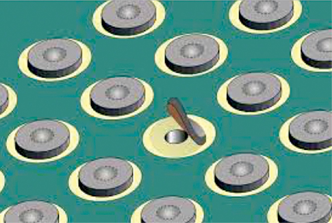
The significance of through holes can’t be ignored by the designers of multi-layered PCBs. This text describes numerous forms of through holes and the way they assist in correct designing of the PCBs.
It’s a well-known truth {that a} PCB is the center of an digital system. {Hardware} engineers have a lot of expectations from PCB designers with respect to sign integrity, energy integrity, electromagnetic compatibility (EMC) in addition to thermal evaluation. Relying upon the kind of circuit, all these parameters must be managed in a PCB design in order to make an meeting profitable for its meant use.
On this digital world the sign velocity ranges from a number of MHz to a number of GHz. With the elevated demand of capabilities per meeting/chip and miniaturisation of digital techniques, PCBs have gotten increasingly advanced. The growing requirement of a number of capabilities in a chip is leading to advanced floor mounted system (SMD) elements, which have a number of pins positioned shut collectively or are even leadless packages. The multi-pin elements like ball grid arrays (BGAs) and skinny quad flat packages (TQFPs) power the PCB designers to go for multilayer PCBs.
Through holes play a serious function whereas designing the multilayer PCBs. A through gap is a plated by means of gap (PTH), which is used to switch a sign from one layer of a PCB to a different layer, with out the scope of mounting any element into these holes.
Most engineers make use of through holes simply to switch alerts. However there are different options too which can be related to these through holes. These through holes can be utilized in numerous methods. A through gap can have a constructive influence in terms of route a sign (interconnection) and a damaging influence in terms of route a delicate sign.
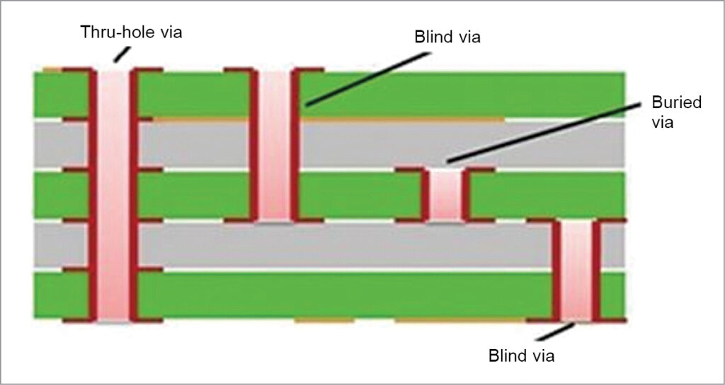
Numerous sort of through holes
By way of gap through, the place one can see by means of a PCB. Such a through gap begins from the highest layer of a PCB and ends on the backside layer. It have to be outlined in each electrical layer of a PCB.
Blind through, whose start line is seen, however finish level just isn’t seen. Such through holes are utilized in multilayer PCBs. A blind through begins from an outer layer and disappears in inside layers.
Buried through, which isn’t seen in any respect. It’s used to switch a sign from one inside layer to a different inside layer. A buried through is used to save lots of the area for sign routing over outer or inside layers.
Micro through, which has a relatively a lot smaller drill diameter. As a consequence of shrinkage of digital assemblies and routing of high-density-interconnection PCBs, through measurement (diameter) is getting lowered. As per IPC, any through gap having drill diameter of lower than or equal to 0.15mm is a micro through. Such through holes are laser drilled.
Through-in pad is mostly used the place it turns into tough to place a through gap in between the pads/land space attributable to limitation of accessible area. On this case, a through gap is drilled inside a land space, and we are able to say that the land space is transformed right into a pad. Such via-hole’s diameter have to be small (as per producer limitations) as there might an opportunity of solder theft on the time of reflow soldering. Parts like invoice grid array (BGA) require via-in pads. (Land space is a copper space with out a gap, the place an SMD element is soldered. A pad is a copper space with a gap within the centre.)
Through for stitching can be used to interconnect giant copper areas on completely different layers. It helps scale back the return path of alerts and thereby preserve low impedance. A through shielding is created by putting a number of rows of through holes alongside the sign route path, which helps in lowering electromagnetic interference (EMI) and crosstalk.
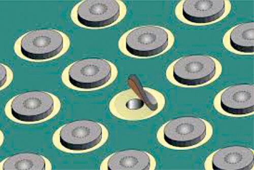
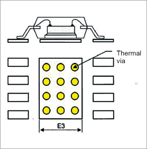
Thermal through is used to enhance the warmth dissipation of surface-mount elements reasonably than transferring a sign. Structurally, a penetrating gap is opened within the board. Thermal resistance is dependent upon the world and thickness of the copper foil on the PCB that serves to dissipate warmth, in addition to on the thickness and materials of the board.
To be able to successfully use thermal vias, it is vital that the thermal vias be situated near heating components, similar to immediately beneath the elements. As indicated in Fig. 4, the impact of thermal equilibrium is utilised, and so it needs to be obvious that connecting areas with giant temperature variations is an efficient plan.
Through holes and sign integrity
In case of low frequency, vias don’t have an effect on sign transmission. As frequency rises (above 1GHz) and sign rising edge turns into steep (1ns at most), nonetheless, vias can’t be merely considered a perform {of electrical} connection, and affect of vias on sign integrity has additionally to be thought of. Vias behave as breakpoints with discontinuous impedance on transmission line, inflicting sign reflections.
However, points introduced by vias focus extra on parasitic capacitance and parasitic inductance. The affect of through parasitic capacitance on a circuit is primarily to delay the rising time of alerts and scale back the operating velocity of circuit. Parasitic inductance, nonetheless, can weaken the contribution of bypass circuit and reduce filtering perform of the entire energy system.
The bigger the through diameter is, the extra discontinuity through will trigger in high-frequency and high-speed PCB designs. It’s tentative data, because it additionally relies upon upon place of energy planes, through gap diameter, plating thickness, and many others. It needs to be saved in thoughts {that a} single through goes so as to add 1-3nH of inductance within the sign. Additional research is required if a designer comes throughout such a scenario. This is named Black Magic over a PCB compared with circuit simulation outcomes.
Present carrying capability of a through
Usually, I by no means advocate switching an influence rail between the layers when designing an influence PCB. Nevertheless, one can use component-mounting pads for a similar. If it turns into mandatory, then use a number of through holes.
As per researchers, calculating present carrying capability of a through gap is a perform of a number of components like, size of through, its drill diameter, placement of energy planes, quantity of energy to be switched between the layers, glass transition temperature (Tg) of PCB base materials, copper plating thickness, and many others. As a thumb rule the completed diameter of a through gap have to be a minimum of as giant because the hint width divided by three. For a digital circuit, using through holes for VCC or Floor is apparent because the quantity of energy may be very much less.
Planning through holes diameter to your design is of nice concern with respect to a producer’s capabilities. You might plan completely different through gap diameter for a PCB as per your requirement.
Commonest drill diameter of a through gap is 0.5mm (20mils), which could be drilled by most PCB producers. If you’re planning something lower than this, you need to test the producer’s drilling and plating capabilities.
With the discount in drill diameter, the spindle velocity of a CNC PCB drilling machine must be excessive. That’s why micro vias are laser drilled as an alternative of mechanical drilling.
Shavinder Singla (CID-IPC, USA), Senior Technical Officer, Centre for Improvement of Superior Computing, Mohali (Punjab)

