An computerized lavatory mild Circuit might be made in a number of methods, relying in your choice and finances. A number of the choices make use of both a movement sensor, a wise change, an occupancy sensor, or a photograph sensor.
The straightforward system proposed right here makes use of a small magnet mounted within the lavatory door’s body and a reed change with usually open contacts because the sensor on the toilet door, simply reverse the magnet. So, everytime you open the door, the reed change will transfer away from the magnet.
Observe: Make sure to seek the advice of a professional electrician should you’re not comfy with electrical work or should you need assistance with set up. Security ought to at all times be your high precedence when working with electrical energy.
Computerized Toilet Gentle Circuit Diagram
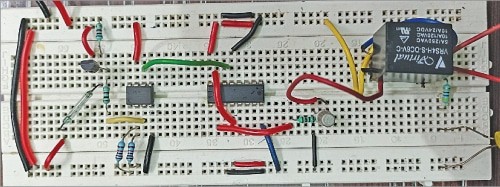
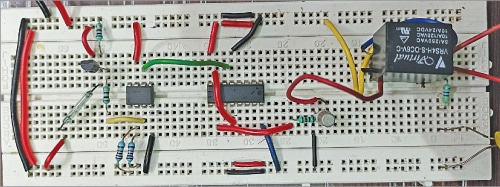
The writer’s prototype is proven in Fig. 1 and the circuit diagram is proven in Fig. 2.
The circuit contains step-down transformer X1, a usually closed kind of reed change, bridge rectifier BR1, transistor BC557 (T1), 5V voltage regulator LM7805 (IC1), a small magnet, op-amp 741 (IC2), decade counter 4017 (IC3), transistor 2N2219 (T2), 5V single changeover relay RL1, and some different parts.

The circuit wants 5V DC o work, which might be derived from the 230V AC main to 9V, 500mA step-down transformer X1. The 9V AC from X1 goes to bridge rectifier BR1 for rectification and is filtered by capacitor C1. The rectified and filtered voltage is regulated to 5V DC by IC LM7805, which is indicated by the glowing LED1.
Computerized Toilet Gentle Working
When the toilet door is closed, the magnet and the reed change are close to one another, reed change contacts are open, and BC557 transistor T1 doesn’t conduct. Therefore voltage at pin 3 of IC2 stays decrease than the reference voltage at pin 2 (round half of the availability voltage), output of op-amp IC2 at its pin 1 stays low, and decade counter 4017 (IC3) doesn’t get any clock sign.

