
A cellphone Sign jammer is an digital machine that blocks the transmission of alerts between a cellphone and a base station. By utilizing the identical frequency as a cellular handset, the sign jammer creates robust interference in communication between the caller and receiver.
It’s efficient in blocking the transmission of alerts from networks together with UMTS, 3G, CDMA, GSM, and PHS.
DIY Cell Cellphone Sign Jammer – Elements Required
| COMPONENT | USAGE |
| Resistor R1 | Emitter Loading |
| Resistor R2 | Base Biasing |
| Capacitor C1 | Frequency Era |
| Capacitor C2 | Suggestions |
| Capacitor C3 | Suggestions |
| Capacitor C4 | Noise Discount |
| Capacitor C5 | Coupling |
| Capacitor C6 | Coupling |
| Capacitor C7 | Decoupling |
| Transistor Q1 | Amplification |
| Inductor L1 | Frequency Era |
Cell Cellphone Sign Jammer Circuit
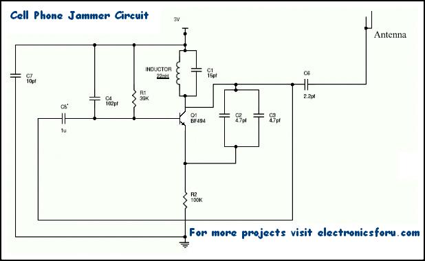
For any jammer circuit, it’s important to have three vital subcircuits.
These 3 circuits, when mixed collectively kind an environment friendly cellphone jammer circuit.
Cell Cellphone Sign Jammer Working
- RF amplifier circuit contains transistor Q1, capacitors C4, C5, and resistor R1. This RF circuit amplifies the sign generated by the tuned circuit. The amplified sign is given to the antenna by capacitor C6. It blocks DC and permits solely the AC part of the sign to be transmitted.
- When transistor Q1 is turned ON, the tuned circuit on the collector turns ON. The tuned circuit consists of capacitor C1 and inductor L1. This acts as an oscillator with zero resistance. It produces very excessive frequency with minimal damping.
- When the circuit is ON, voltage is saved within the capacitor. As soon as the capacitor is totally charged, it permits cost to movement by the inductor. When present flows by the inductor, it shops magnetic vitality similar to the voltage throughout the capacitor. At a sure level, the inductor reaches its most and the cost or voltage throughout the capacitor turns to zero.
- Now the magnetic cost by the inductor decreases and the present prices the capacitor in reverse or reverse polarity. The method repeats and after some time, the inductor prices the capacitor and turns into zero.
- This course of runs until inside resistance is generated and the oscillations cease. RF amplifier feed is given by capacitor C5 to the collector terminal earlier than C6. The capacitors C2 and C3 generate pulses in a random trend (noise) on the frequency generated by the tuned circuit.
- The RF amplifier boosts the frequency generated by the tuned circuit. The frequency generated by the tuned circuit and the noise sign generated by the capacitors C2 and C3 is mixed, amplified, and transmitted.
Cellular Frequency Jamming Calculation
Cellphones function at completely different frequency bands in numerous international locations. For Canada, the 1900 MHz band is the first band, significantly for city areas. 850 MHz is used as a backup in rural areas. The USA makes use of 850 and 1900 MHz bands, relying on the world. Europeans have a tendency to make use of the GSM 900 and 1800 bands as customary. Center East, Africa, Asia, and Oceania additionally use these frequency bands. In Russia and another international locations, native carriers have licenses for 450 MHz frequency to supply CDMA protection.
Using completely different frequencies makes it tough to have a jammer for all frequencies. Nonetheless, the below-mentioned system can be utilized to calculate the required values.
F = 1/(2*pi*sqrt(L1*C1))
Relying on the frequencies it is advisable to block, the values of the inductor (L1) and capacitor (C1) may be altered.
For instance, if cell phones in your space work at 450 MHz, it is advisable to generate 450 MHz with some noise to behave because the blocking sign.
Now the cellphone receiver will be unable to grasp, which sign to obtain. We’ve efficiently blocked cellphone alerts.
Right here, 450MHz is the tuning frequency. Cellphone jammers for different frequency ranges are designed equally. Nonetheless, the sign vary could be very weak. Thus, this circuit works just for a spread of 100 m.
Be aware
- This circuit can block alerts solely inside a 100-meter radius.
- Utilization of this sort of circuit is banned and unlawful in most international locations.
- This circuit can be utilized in TV transmission and remote-controlled toys.
- If the circuit shouldn’t be working correctly, strive growing the resistor and capacitors values within the circuit. Use the system given above.
- The ability provide for the circuit mustn’t exceed 3 Volts.
We’ve extra such fascinating DIY Electronics Tasks for you.
Be aware: The cellphone jammer is an untested prototype circuit and is banned in a number of international locations. Maintaining in with these laws, we would not have the option that can assist you out with the precise values.
This text was first printed on 17 October 2017 and lately up to date on 09 December 2022.

