In some locations, particularly in growing international locations like ours, sudden ups and downs within the mains voltage are fairly widespread. This generally causes a critical failure {of electrical} home equipment like tv units, air-conditioners, and fridges, which aren’t designed to tolerate decrease or greater voltages past a small restrict. So you will need to use overvoltage and undervoltage safety for electrical and digital home equipment. 
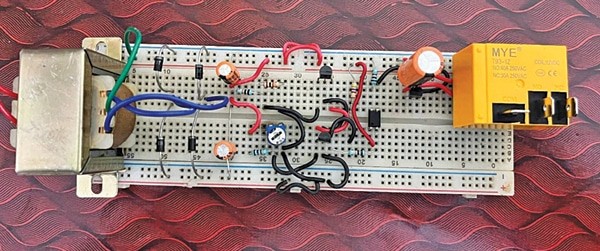
This circuit incorporates a low-voltage and high-voltage tripping mechanism to guard the home equipment from any injury because of voltage fluctuation. The writer’s prototype on the breadboard is proven in Fig. 1. The circuit diagram is proven in Fig. 2.
Overvoltage Safety Circuit Diagram
The circuit’s twin energy provide utilizing transformer X1 and diodes D1 by means of D4 isolates the availability between relay RL1 and management circuitry with the assistance of optocoupler IC PC817. It helps to get rid of the voltage-dropping drawback when the relay energizes. The capacitors C1, C2, and C3 are used to smoothen the rectified pulsating DC from the diodes.

The ICs IC1 and IC2 (TL431) are adjustable shunt regulators. The R1-R2 resistor voltage divider community is used to set the higher cut-off voltage and preset VR1 is used to set the decrease cut-off voltage. Diode D5 works as a freewheeling diode and transistor T1 is used to drive the relay. Resistor R6 biases the interior transistor of the optocoupler and resistor R4 is used to bias the interior transistor of IC2.
| Elements Record | |
| Semiconductors: | |
| IC1, IC2 | -TL431 shunt regulator |
| IC3 | -PC817 optocoupler |
| D1-D5 | -1N4007 rectifier diode |
| T1 | -BC337 NPN transistor |
| Resistors (all 1/4-watt, ±5% carbon), except said in any other case: | |
| R1 | -9-kilo-ohm |
| R2 | -1.2-kilo-ohm |
| R3 | -1-kilo-ohm |
| R4 | -4.7-kilo-ohm, 0.5W |
| R5 | -10-kilo-ohm |
| R6 | -1-kilo-ohm |
| VR1 | -10-kilo-ohm preset |
| Capacitors: | |
| C1, C2 | -100µF, 35V electrolytic |
| C3 | -1000µF, 35V electrolytic |
| Miscellaneous: | |
| X1 | -230V AC major to 12V-0-12V, 500mA secondary |
| RL1 | -12V single changeover relay |
| CON1, CON2 | -2-pin terminal connector |
| -3-pin terminal connector | |
The secondary voltage of transformer X1 proportionally modifications as the first (AC mains) voltage modifications. This transformation displays on the exterior reference pins (pin 1) of IC1 and IC2. The R1-R2 resistor community units the pin 1 voltage under the interior reference voltage of IC1.
IC1 acts as an open circuit that exists between cathode pin 3 and anode pin 2 of optocoupler IC3. Preset VR1 is adjusted to set the pin 1 voltage of IC2 above the interior voltage reference of IC2. On this case, IC2 acts as a brief circuit and so the optocoupler retains conducting.
The optocoupler output biased by means of R6 is fed into the bottom of transistor T1, which drives relay RL1 to on state. If the voltage will increase and turns into better than the interior reference voltage at pin 1 of IC1, the optocoupler begins conducting between pin 3 and pin 2 and acts as a brief circuit. This units IC2’s reference pin 1 under the interior reference voltage and forces IC2 to an open-circuit state, so the optocoupler and relay flip off and change off the load. The identical occurs when the voltage decreases at pin 1 of IC2 because of a fall in AC mains voltage.
Development and Calibration


An actual-size, single-side PCB structure for the circuit is proven in Fig. 3 and its part structure is proven in Fig. 4. After assembling the circuit on PCB, enclose it in an acceptable field. Repair VR1 outdoors the field after correct calibration (if utilizing a pot rather than preset). Match the transformer contained in the field.
For the calibration, chances are you’ll use a variac (variable transformer) for setting the over-voltage and under-voltage limits. The over-voltage restrict has been set round 270V with the assistance of resistors R1 and R2, which you’ll be able to change (if required) by altering the values of those two resistors.
For the under-voltage restrict, set the variac to round 180V and set the preset in such a approach that the relay energizes at this voltage. This completes the calibration.
After calibration, enclose the field and join the 230V AC mains voltage to the first of transformer X1. Join the AC mains and the equipment to be protected throughout connectors CON1 and CON2, respectively. Now your circuit is able to use.
Obtain PCB and Part Structure PDFs: click on right here
Shamail Ahmad is B.E. (ECE) and has 12 years of expertise in Electronics R&D. He’s working as CTO at Harlen Automation Non-public Restricted, New Delhi

