
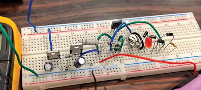
 This easy battery charger, with overcharge safety, can be utilized to cost a number of cells in a battery. It signifies when the cells are absolutely charged. The charger requires minimal elements, which may be procured simply. The creator’s circuit wired on a breadboard is proven in Fig. 1.


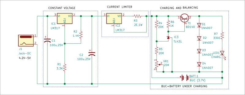
The circuit of the Li-ion battery charger, proven in Fig. 2, has three elements—charging and balancing circuit, present limiter, and fixed voltage supply. The circuit is able to offering a most of 1.5A present and may take enter as much as 27 volts.
Charging and balancing circuit
When the voltage throughout Zener diode TL431 is beneath the edge voltage, the Zener is in off state. Because the base of the transistor is linked to the cathode of TL431, the transistor stays in off stage as properly. Subsequently, the present flows by means of the battery, which is linked in parallel, and thus begins charging it.
On the completion of charging, when the voltage of the battery rises over the higher threshold voltage, the TL431 will get activated and connects the bottom of the transistor to the bottom, thus turning the transistor to its conducting state. On this state, the transistor creates a brand new path for the present to circulation, bypassing the battery, and so the charging stops.
The transistor is linked in collection with 4 diodes, which act as a load. The diodes are additionally linked to a resistor and an LED in parallel to them. When the transistor is conducting, the present flows by means of the 4 diodes and the LED concurrently, thus turning on the LED to point that the battery is absolutely charged.
The circuit additionally provides a cell balancing function, which is essential after we cost a battery with a number of cells in collection. With the cells linked in collection, we have to be sure that the full voltage of the battery pack after charging doesn’t exceed the utmost specified voltage of the battery pack. Additionally, the voltage of every charged cell shouldn’t exceed the utmost specified voltage of that particular person cell.
Present limiter circuit
Each cell has a most restrict of charging present it might take, which is denoted by its C-rate. The C-rate of a cell depends upon a number of components, akin to its chemistry, dimension, inside construction, and so on. Charging with overcurrent might trigger irreplaceable harm to the cell and can also trigger thermal runaway within the battery, which may end up in a hearth. Subsequently, IC LM317 is used as a present limiter.
As proven in Fig. 2, the voltage enter pin VI of LM317 is linked to the optimistic of the supply, and voltage output pin VO is linked to resistor R3. The regulate pin ADJ is linked to the opposite finish of the resistor. The worth of present I_out may be adjusted by altering the worth of resistor R3, as per the connection given beneath. Although, for this charger, we’ll maintain the utmost output present (Iout) as 0.6A.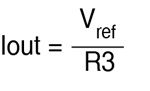
Right here, Vref is 1.25V.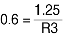
R3 is 2.08 ohm
Fixed voltage supply
To make the circuit extra versatile and make it work over a large voltage vary, we make use of voltage management by utilizing one other LM317 IC. The enter terminal VI of this IC is linked to the bottom by means of capacitor C1, which must be stored as shut as attainable to the enter terminal. The regulate pin ADJ of the IC is linked to the Vout with resistor R2 in between and to the bottom by means of resistor R1.
To enhance the transient response of the output, capacitor C2 is linked throughout Vout pin of the IC and the bottom. The output voltage of IC1 may be adjusted as per following relationship: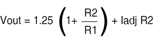
Because the worth of Iadj could be very small, it’s going to have little impact on the output voltage. For a single cell Li-ion charger, the worth of resistor R1 and R2 could be 3.3k and 1.4k, respectively. The values of R1 and R2 should be modified for reaching totally different voltages for various cell chemistries or totally different battery configurations.
| Components Listing | |
| Semiconductors: | |
| IC1 | – LM7812, 12V voltage regulator |
| IC2 | – 4027 twin flip-flop IC |
| BR1 | – 1A bridge rectifier |
| T1 | – BC557 pnp transistor |
| T2 | – SL100 npn transistor |
| D1 | – 1N4007 rectifier diode |
| LED1 | – 5mm LED |
| Resistors (all 1/4-watt, ±5% carbon): | |
| R1, R6 | -1-kilo-ohm |
| R2 | – 100-kilo- ohm |
| R3, R4 | – 10-kilo-ohm |
| R5 | – 18-kilo-ohm |
| Capacitors: | |
| C1 | – 1000μF, 35V electrolytic |
| C2 | – 1μF, 25V electrolytic |
| C3 | – 0.1μF ceramic disc |
| Miscellaneous: | |
| LDR1 | – Mild dependent resistor (LDR) |
| RL1 | – 12V, 1CO relay |
| S1 | – Foot swap |
| X1 |
– 230V AC main to 15V, 500mA secondary transformer |
| CON1-CON3 | – 2-pin terminal |
| – Torch or laser gentle | |
Building and testing
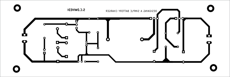
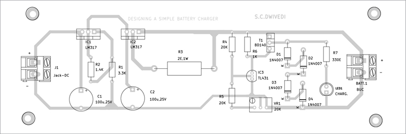
An actual-size, single-side PCB for the charger circuit is proven in Fig. 3 and its element structure in Fig. 4. After assembling the circuit on PCB, enclose it in an acceptable field. Join the enter throughout J1 and the battery underneath cost (BUC) at BATT.1.
For setting the edge voltage for the adjustable shunt regulator, instead of the cell join a regulated energy provide. Hold the output voltage the identical as the edge voltage you need to maintain as cutoff voltage for the cell. Now, flip pot VR1 till LED1 begins glowing. That is the cutoff voltage at which the circuit will bypass the cell and present will begin flowing by means of the collection of diodes.
You should use the identical circuit for charging totally different cell chemistries, akin to lithium ion phosphate (LFP), lithium nickel manganese colbalt oxide (NMC), and even lithium-ion polymer (Li-Po) batteries, by setting the cutoff voltage for the adjustable shunt regulator TL431.
Charging a couple of cell
To cost greater than a single cell, that are linked in collection, we have to replicate the charging and balancing circuit in collection. The connections for a 3-cell charger are proven in Fig. 5.
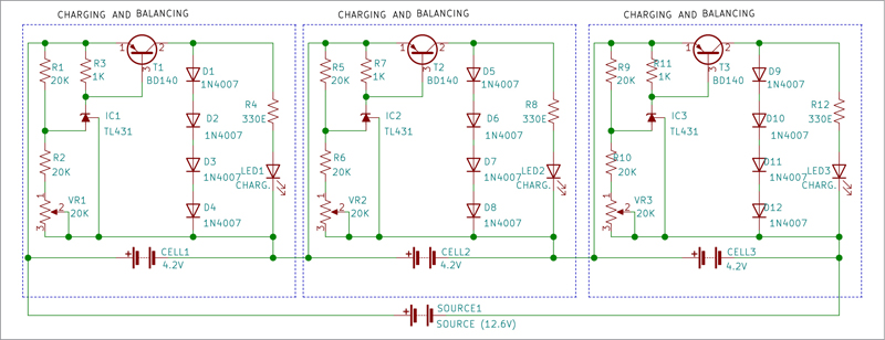
From Fig. 5 it’s clear that the charging and balancing circuits are linked in collection with one another and the entire collection is linked in parallel to an influence supply. The cells that should be charged are linked individually to a charging circuit every.
Because the cells might take totally different instances to cost and discharge, the voltage of every cell within the battery pack will not be the identical. Therefore, when one of many cells is charged, the edge voltage of TL431 in that particular circuit is reached and the cell in that circuit is bypassed, so the present flows by means of the 4 diodes in collection and the indicator LED activates.
Bonus. You may watch the video of the tutorial of this DIY undertaking at
Obtain PCB and Element Format PDFs: click on right here
The creator, Sharad Bhowmick, works as a Expertise Journalist at EFY. He’s captivated with energy electronics and power storage applied sciences. He needs to assist obtain the objective of a carbon impartial world.