Purposeful mills and logic analyzers each are vital instruments for all electronics engineers and more often than not we want they need to be so small that we will carry them any had been and the additionally so at this time we’ll such a software that may work as a logic analyzer and performance generator as nicely and is so small which you could carry in a pocket. Right here we’ll design 4 channel logic analyzer and mix it with a separate practical generator. So let’s begin our design with a group of the next parts,
Invoice Of Supplies

Coding
Logic Analyser
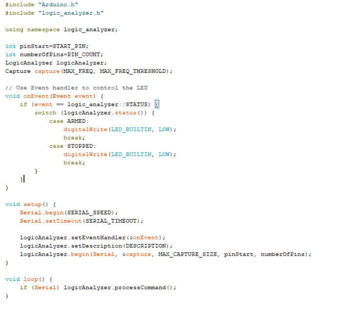
First we have to make the code so our ESP 8266 act as logic analyzer right here we will make 4 GPIO of ESP into LOgic analyzer so you may say we’re going to make 4 channel logic analyzer utilizing which we will see the enter sign so first, we have to put together the Arduino IDE and set up ESP 32 and ESP 8266 board to Arduino IDE for which you could discuss with the official ESP web site after putting in the ESP boards to Arduino IDE we are actually able to program, Now obtain the logic analyzer library and add it to Arduino IDE utilizing library supervisor or you may merely extract the zip file of the library within the library folder of Arduino and the library robotically get added.
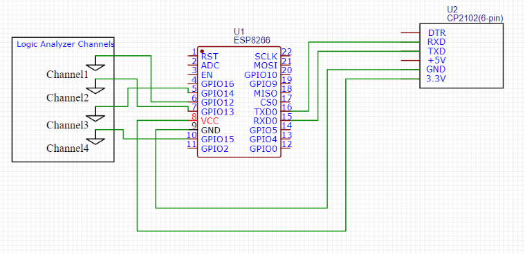
Now we will do coding right here in code we will set the frequency and pattern quantity after which choose the best port and board ie ESP 8266 12. And join the ESP RX TX pins to FTDO TX RX pins and VCC to ESP 12 F 3.3 V pin of FTDI and GND to GND after which GPIO 0 to GND and add the code to ESP 12 F.
Purposeful Generator
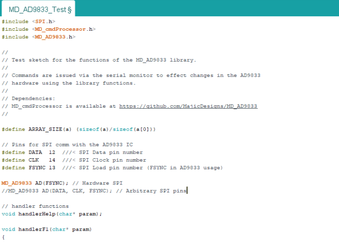
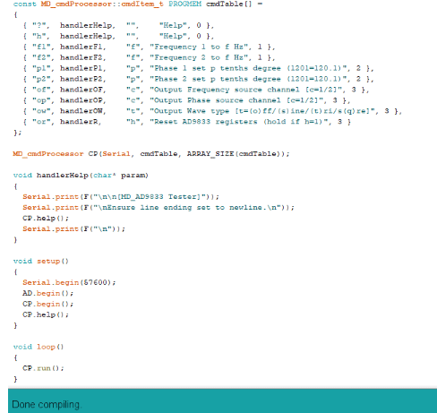
Now we have to create the code for the perform generator right here we go to sketch after which open library supervisor and search AD9833 after which set up the library for the practical generator now we will create the code within the first a part of the code we have to set the SPI pin numbers in code for reference to our AD 9833 practical generator after which the opposite capabilities in code choose the best board and pot quantity and add the code like we do in earlier ESP8266 board . Now our gadget is prepared.
Connection
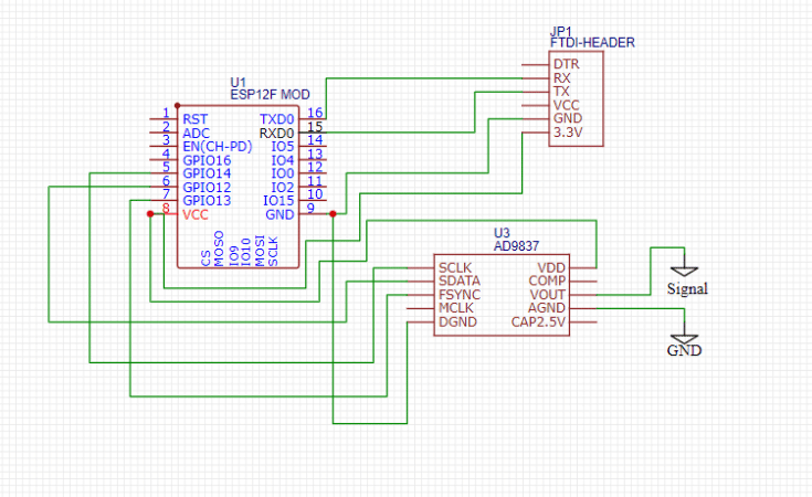
Now join each esp with parts as in circuit diagram the place one ESP act as logic analyzer and different act as practical generator mix each exp and put in single enclosure and now our Logic analyse and practical generator is prepared .
Testing
Now our logic analyzer is prepared, however our gadget can seize the logic knowledge utilizing GPIO pins, which act as a channel for the logic analyzer, however we will’t view it with none software program, so you probably have a PC or laptop computer, then set up the Sigrok utilizing the next hyperlink.
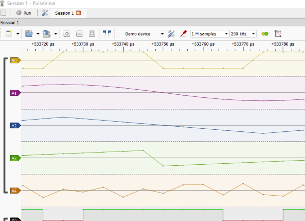
Now open the Sigrok Pulseview after which go to attach and choose the Open Bench logic snipper. Now, choose the serial port and baud fee after which scan for the gadget. After scanning, you’ll obtain the identify of the logic analyzer gadget. The identify used for this gadget is the ESP board. It exhibits ARDUINO ESP with 4 channels. Choose it, and now your 4-channel logic analyzer is prepared. Now you may join the enter of the logic analyze channel ie pin 12 13 14 15 of ESP to see the indicators to learn the small print of the sign you may discuss with the next hyperlink.
For the practical generator plug FTDI for the practical generator after which open the serial port in Arduino and now ship “?” to the gadget in return it exhibits you instructions you do now choose the wave kind you need to generate and the frequency of wave and now your wave is generated and the output may be acquired on the out pins of the practical generator as in circuit diagram.

